Electronic Components
| In the 1920's there were large
numbers of radio kits on the market. These were popular as
they were a lot cheaper than the ready built receivers, and
attracted a lot of interest. Many enthusiasts built their
own receivers, and magazines featured designs that anyone
could build from the readily available bits and pieces. To
cater for this rapidly growing market, A.J.S. sold many
components separately. All of them carried the A.J.S. name
and most of them were produced in Wolverhampton. |
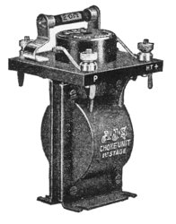 |
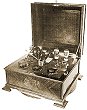
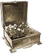
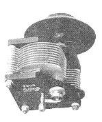
A.J.S. sold a range of chokes for various uses. The
photograph opposite shows the first stage choke unit that
was used with the detector valve in a receiver. It includes
the grid capacitor and grid resistor, and sold for £1.
There was also a 2nd stage choke unit, for use in
coupling stages of an audio amplifier. It also sold for £1.
The choke was available on its own for 15s.0d. |
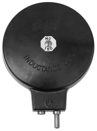
| A.J.S. produced a range of tuning coils for use with A.J.S.
tuning capacitors. The coils were 3.5" in diameter and had a
standard plug and socket fitting. |
A list of available coils, and prices from
1926.
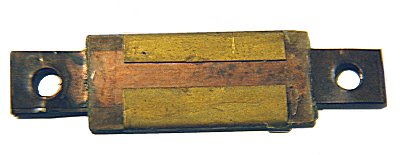
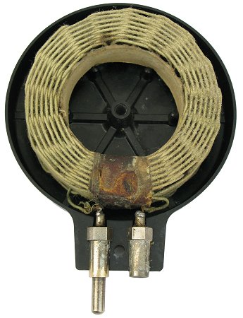
| The coil number refers to the
approximate wavelength (divided by ten) of
the self-resonant frequency of the coil, so
coil number 150 self-tunes to around 1,500
metres = 200 kHz. The inductance of the
coil, assuming an internal capacitance of
10pF is 63mH. The coil below, a number 50,
has an inductance of about 7mH. |
|
 |
|
 |
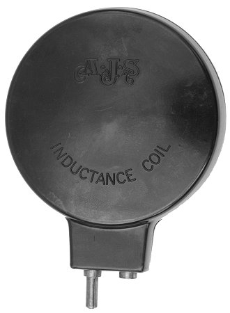
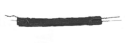
| The
coils were wound from cotton insulated
copper wire, and impregnated to make them
moisture proof. This is an A.J.S. coil
number 50. |
|
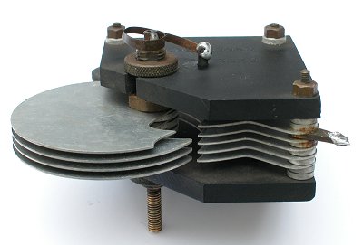
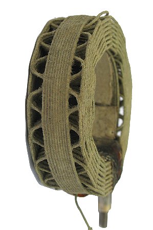
This
view of the coil shows the method of
construction which produced a low
capacitance winding. |
|
|