This is an account of how mill
rolls were produced. On the following pages (linked at the
bottom of this page) are photographs from a book produced by
Perry's which illustrate this process. These photographs
are referred to by their numbers in this account.
The production process
can be said to start with the making of the patterns (wooden
replicas of the necks and wobblers of the rolls) and sweeps (for
grain rolls) (See photographs 1,2 and 3). Sweeps were
profiled wooden boards used for moulding rolls, which were cast
with their profiles.
The neck and wobbler
patterns were placed in moulding boxes and sand rammed hard
around them. (See photographs 4 and 5) When all the sand
had been added the patterns would be withdrawn leaving a neck
and wobbler shaped void into which the metal would be cast when
the final mould assembly took place.
The method of making
grain rolls using sweeps is described alongside photograph 3.
Once the mould had been
made and assembled the melting process could begin. The furnaces
were charged with a mixture of lumps of scrap roll (worn out
rolls bought back from the customer) (See photograph 8),
surplus metal from previous casts, the heads and gates from
previous casts, and pig iron.
The weights and chemical
composition of each of these various components of the
charge were established and a great deal of careful
calculation done by the metallurgists to ensure that the mix was
such as to provide a chemical composition as near as possible to
that demanded by the nature of the rolls being cast. (See
photograph 31)
Chemical constituents
included carbon, silicon, manganese, nickel and chromium. It was
necessary to calculate the charge so that the minimum of
alloying additives (which were expensive) would need to be added
to the furnace to obtain the correct composition.
The furnaces were
reverbatory furnaces fired by pulverised coal. [A reverbatory
furnace is one in which the fuel is not in direct contact with
the charge, the heat generated by the burning fuel bouncing-
reverberating- from the furnace walls onto the charge.]
Once the furnace was
charged- the furnaces shown had removable tops so that the
charge could be loaded by crane – and the tops replaced, the
pulverised coal was drawn from the silos (see photograph 9)
by a system of pipes to the furnace burners where it was blown
into the furnaces as a jet of coal dust and air.
The coal/air jet was lit
and the heat produced by the burning jet of coal dust and air
heated up the furnace and after a while caused the metal to
melt. The metal would only be tapped from the furnace when it
had reached the desired temperature for the particular metal
composition and roll type. (See photographs 10 and 11)
How long a charge took
to melt and attain the desired temperature depended upon a
variety of considerations: the weight of the charge; the tapping
temperature needed etc., but was certainly several hours. The
furnaces would be fired up early in the morning (perhaps at
around 6.00am) and it might be 1.00pm or 2.00 pm before the
furnace was ready to tap.
The furnace would then
be tapped out as shown in photographs 12 13 and 14 and
cast as shown in photographs 15 and 16.
After casting, the mould
would have to be left for some while (in the case of the large
rolls for perhaps 3 days) to allow the casting to cool
sufficiently to be removed, partly because of the danger and
discomfort to the workers involved and partly because if done
too soon the thermal shock of the cold air on a hot casting
might cause it to fracture.
The moulding boxes and
chills (where used) would be removed by a small gang of men
called “Strippers”, the gate broken off the casting and
the casting lifted by crane to one end of the foundry, when
adherent sand would be removed using a pneumatic chisel and
powered grinders. The man who did this was called the “Dresser”.
The casting would then be transferred to the machine shop for
machining. (See photographs 17 to 30)
Some rolls would have to
be annealed before machining. This involved placing them in gas
fired annealing furnaces and heating them slowly to a
temperature well below the melting point and then allowing them
to cool in a controlled manner over days. The purpose of
annealing was to alter the metal structure by the heating and
cooling process and so make them more resistant to the shocks
which they would encounter when in service in the mills.
The following photographs, which appeared
in the book which Perry's published in 1967, to mark the
modernisation of the plant, give a good idea of how mill rolls
were produced.
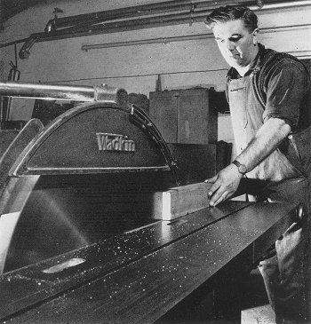 |
1. Using the circular saw to cut timber for
patterns.
The pattern maker is Roy Miller.
|
|
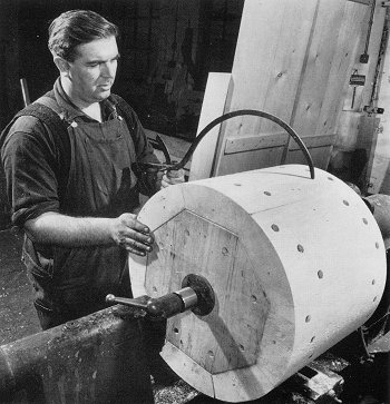
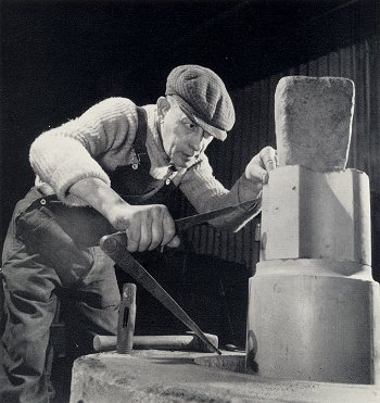
2. Shows the pattern maker, Roy Miller, checking the
dimensions of a wooden pattern for a roll neck. |
 |
 |
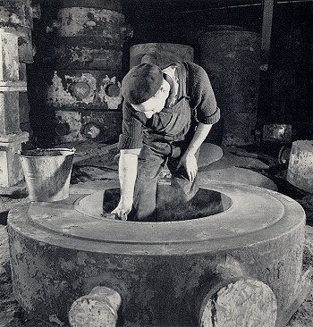
3. Shows Isaiah Wellings beginning to mould a section of a
grain roll. |
|
A grain roll was a
relatively soft sand cast roll, cast with its profile.
Grain rolls were used in the mills for initial rough forming of
steel. The mould was made in sections using a sweep- a wooden
board cut to the profile and size necessary. A moulding box was
placed on a metal base plate on the foundry floor and the sweep
bolted to a rotating central spindle [these are clearly seen in
the photo] Iron bricks (called denseners) were built up and sand
packed between them, the sweep being rotated to ensure that the
correct profile was being maintained. When all the denseners had
been placed a coat of loam (always pronounced “loom”) was
applied by hand. This was a thick paste of sand and various
binders (special clays etc). [In the old days horse manure was
added to the loam mix to give added binding power but I cannot
recall this being done during my time]
The sweep would be
rotated again as necessary until the moulder was satisfied that
the correct dimensions and profile had been produced. The mould
section would then be removed and dried in coke fired ovens
[always called stoves] for perhaps two or three nights. Once
dry, the various sections would be brought to the casting pits
and assembled to form the finished mould. |
|
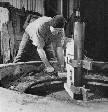
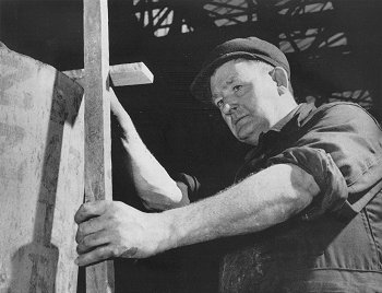
4. Shows the moulder,
Tommy Morris, checking that the pattern for a “wobbler” is correctly
set in the mould before beginning to mould the sand around it.
The wobbler was essentially the means by which the roll was
connected to the mill drive when installed in the mill. [If I
remember right not all rolls had wobblers- some had spade ends (see
photo on page 55 for illustration of spade ends) I think that it was
probably the strip and plate mill rolls which had spade ends rather
than wobblers.] |
 |
 |
5. Shows the beginning
of the moulding process for the neck of a roll.
The moulder, Walter Jayes,
is checking that the wooden pattern is level and at the correct
height.
|
|
6. Shows a large chill
being sprayed with a carbon black solution. This was to prevent the
molten metal adhering to the chill during casting.
A chill is a cast iron
cylinder of suitable diameter, used to make the mould of the body of
certain kinds of rolls [known as chill rolls] The purpose of the
chill was, as its name rather suggests, to cause very rapid cooling
of the molten metal during casting, producing a very dense metal
structure at the cast surface and imparting a hard-wearing surface
to the body of the roll.
I cannot remember the name of the worker. |
 |
 |
7. Shows a small chill
being dressed. A slurry of sand and binders was applied with a
brush. Again the purpose was to prevent the molten metal adhering to
the chill during casting.
The chill dresser is Ron
Smith.
|
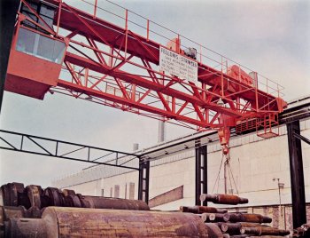 |
8. Shows the scrap gantry to the rear of the foundry. This
gantry was installed as part of the mid-60s modernisation. |
|
Not seen in the photograph is the breaking pen. This was a
circular enclosure of heavy steel plate (lined I think with
baulks of timber). Scrap rolls would be lifted by the crane into
this breaking hole and then a heavy steel ball dropped from the
crane onto the rolls, thus breaking them into pieces suitable
for charging to the furnaces.
Perry’s prided itself on having very low production scrap rates
so virtually all of the rolls seen in the scrap gantry would
have been worn out ones purchased from the customer for
remelting to make new rolls. |
|
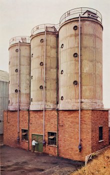
9. Shows the silos
used to store the pulverised fuel which fired the furnaces after the
modernisation.
The coal (ready pulverised)
was delivered by tanker from James Durran of Penistone, Yorks and
pumped into the silos. From the silos it was transferred by pipes to
the furnace burners as needed. |
 |
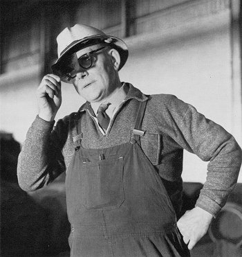 |
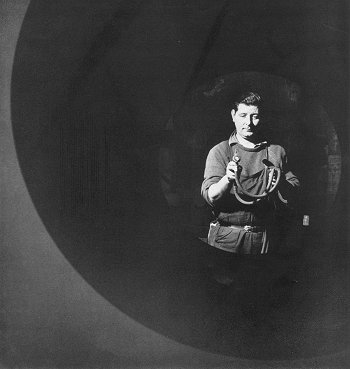
10. Shows the furnace
chargehand, Harold Hall, looking into a furnace through a piece of
blue glass.
Furnacemen of long standing- like Harold -
claimed to be able to judge the temperature of the molten metal in
the furnace nearly as accurately as could be measured by an
instrument, simply by looking at the colour of the metal and
applying their experience. |
|
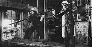
11. Shows the
temperature of the molten metal (the “bath”) in a furnace being
taken.
Holding the pyrometer is Bill Farrell, Chief Metallurgist. Standing
next to the furnace is Bill Mullinder, furnaceman. |
 |
|
The long pole like object is a pyrometer, an instrument
specifically used for measuring molten metal temperatures. The
cable seen trailing from the rear goes to a recorder which
traces the temperatures on a paper chart. |
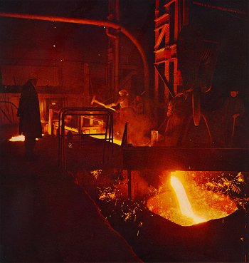 |
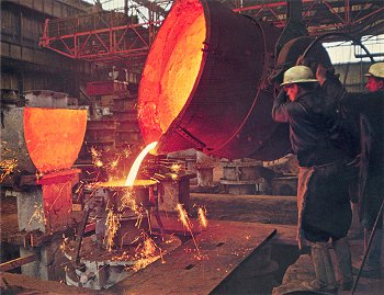
12. Shows one of the
new furnaces (i.e. post the 1960s modernisation) tapping out into a
ladle.
Each furnace had a hole at
the bottom of the base from which the molten metal would run.
Before melting began this hole would be plugged with sand. When the
melt was of the right temperature and composition the crane-held
ladle was dropped into position and the sand plug removed by using a
long pointed steel bar [This was tapping out]. The molten metal was
then free to run from the furnace into the ladle. |
|
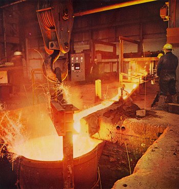
The man shown wielding the hammer is driving down the steel
gates in the runner channel to hold back much of the slag which
emerges at the end of the tap-out, while still allowing the
remaining metal to flow into the ladle. [The slag is
lighter than the molten iron so floats on top of the iron in the
furnace- as the last of the molten metal runs out so does the
slag.] |
|
13. Another view of a furnace tapping out into a ladle. |
 |
 |
14. Another view of a furnace tapping out into a ladle. |
|
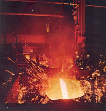
15. Shows a roll being
cast.
The rolls were cast standing on end in casting pits. The box into
which the metal is being poured was called the receiver. From there
the molten flowed vertically down through a part of the mould called
the gate [always pronounced “git”] and entered the main body of the
casting from the bottom. |
 |
|
Although it cannot be seen from the photos the git was moulded
in such a way that the metal entered the bottom of the roll
mould at a tangent. This caused the metal to spin as it rose up
the mould, sweeping any slag and debris into the centre and
rising to the top. This was so that debris etc would not cause
defects on the face or in the body of the casting. |
 |
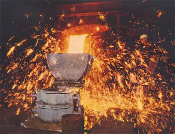
16. Shows the final
stage of the cast, topping up the head. The ladlemen here are Billy
Elbro (on the left) and Arthur Billingsley.
The head was at the very top of the mould. Its purpose was to
provide a reservoir of metal which would remain molten for longer
than the main body of the roll and so feed metal down as cooling and
contraction took place, thereby eliminating voids in the finished
casting which would have had a very deleterious effect. |
| Exothermic compounds were shovelled onto
the head to help the metal in it stay molten longer.
Casting was one of the most skilful parts of
the roll founding process. There was no question of delivering a
weighed amount of metal to the mould; all was done by judgement
and experience. Clearly the mould had to be filled to the top,
i.e. the head, but equally clearly it was highly undesirable to
put so much metal in that the head overflowed sending quantities
of molten iron over into the casting pit and presenting a real
risk of burns to anyone in the vicinity.
Each cast was controlled by the Foundry
Superintendent or Foreman who (while the metal was being poured
into the receiver) stood on the metal plate shown in front of
the mould (protected from splashes and sparks by a hand held
wooden shield) and watched the metal rise up the mould. When he
judged that there was sufficient metal to fill the mould
including the head (and taking into account the quantity of
molten metal still in the receiver) he would call “Up” to
the ladlemen and they would then swing the ladle back upright,
so stopping any further metal entering. Notwithstanding all the
experience of the Superintendent or Foreman, sometimes he called
“Up” a little too soon and then the head had to be topped up.
This is what seems to be happening in this picture. A large part
of the skill in correctly calling the ”Up” was not simply
judging how much metal had already gone in but how quickly the
ladlemen could swing the ladle upright. This would depend upon
the size of the ladle (a big ladle would move much more slowly
than a small one) and even on the characteristics and strength
of the individual ladlemen. |
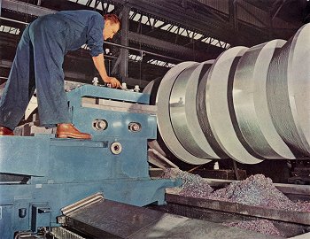
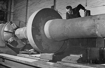 |
17. Shows a beam roll
being machined in the machine shop. The machinist is Norman
Willis(?)
A beam roll was used to
impart the H or I section to steel in the mill. A beam roll would be
set vertically in the mill to produce this section. |
|
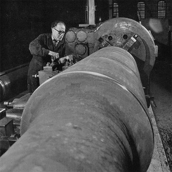
18. Shows a strip mill
or plate mill roll being machined.
I cannot remember the name of the machinist. |
 |
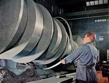 |
19. Shows a grain roll being machined. The machinist is Norman
Willis(?). |
|
20. The same, taken from a different angle. |
 |
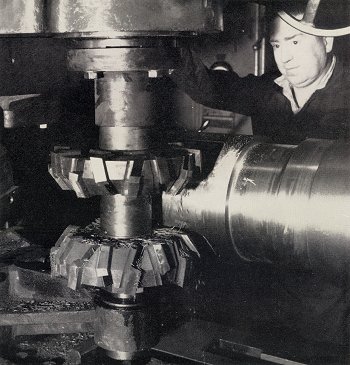 |
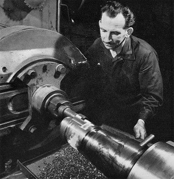
21 A small chill cast roll
being machined. The operation here seems to be machining wobblers.
|
|
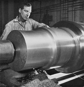
22. A small chill cast
roll being machined.
|
 |
 |
23. What seems to be a plate or strip mill roll being
machined. |
|
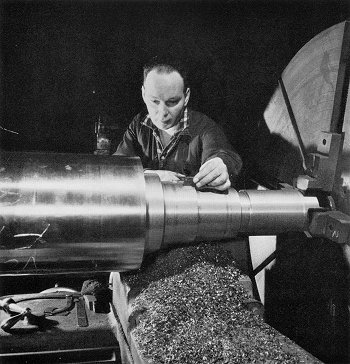
24. A small chill cast
roll being machined. I think the machinist is
Cyril Darby. |
 |
 |
|
 |
|
|
Return to
Later
Company History |
|
Return to
the contents |
|
Proceed to
the
Production Process 2 |
|