|
Front Stairs; Forward Engine;
77 Seats
The Guy
Wulfrunian Air-Suspended Bus Chassis
by John M. Dickinson-Simpson
Extracts from a technical
leaflet issued by Guy Motors in 1959 |
|
Guy
Motors Limited claims to have introduced the most technically advanced
passenger service vehicle yet made available to bus operators. The claim is
not altogether an idle boast, for whereas there are some continental and
American bus chassis with air springs and independent front suspension,
there is no production chassis offered which allies these features with disc
brakes.
Those same basic features of air suspension and disc
brakes also, of course, apply to the Guy 'Victory Airide' single decker
chassis introduced at the last Earls Court Show. But with the 'Wulfrunian' chassis, Guy has gone
further. All lubrication points except those on the propeller shafts have
been eliminated. Successful efforts have been made to lighten the steering
without the introduction of power assistance. Various air pipe lines have
been grouped together as far as possible and are to be coloured for easy
identification. A Cave-Browne-Cave combined saloon-heating and
engine-cooling system which eliminates the usual radiator has been
incorporated. And the brakes are operated by solid-line hydraulics right to
the footbrake pedal: failure of the air-pressure assistance will not destroy
the foot brake action.
|
The side elevation of the Charles H. Roe all-metal
body, seating 75 passengers.
|
However, it is the overall concept of the 'Wulfrunian'
that has captured the imagination of those British operators who have been
in on the design from the beginning and have offered their advice.
The chassis has been designed in the first
place for a 30 ft. long, front entrance, low height, 75 to
77-seater double decker body with a flat lower saloon floor, and
a centre aisle upper saloon seating layout. |
 |
| There is a 7 ft. l in. front overhang to accommodate a wide
entrance and exit ahead of the front wheels, and in this the
vehicle is unique among forward-engine designs. Opposite this
front entrance, and forming a division between the
passenger circulating platform and the driving compartment, is a
vertical engine, which at present can be of either Gardner or
Leyland manufacture. |
| The prime feature of the 'Wulfrunian' chassis layout is its
versatility. An entrance anywhere else along the length, other
than the front could be accommodated, or indeed a front entrance
in combination with a rear exit, as is favoured by one or two
British municipalities and is popular overseas as a single-deck
layout. |
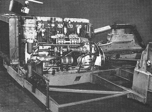
The engine. |
The offside half of the front panelling
swings back to give ready access to the front of the engine. |
The Wulfrunian chassis is not intended only for
double decker bodies, however It is also considered suitable for
single deckers. As such it is expected to have appeal for city bus operation
where a single step, a constant-level flat floor and a wide entrance might
be expected to result in considerably improved passenger flow, and thus
offer operational advantages offsetting the loss of at least four seats on
account of the inevitably deep front wheel arches. |
|
The engines offered as the standard alternatives are
the Gardner 6L W 8.4 litre (358 lb-ft. maximum torque), the Gardner (6LX
l0.45 litre (485 lb-ft.), the Leyland O.600 9.8 litre (410 lb-ft.) and the
Leyland O.680 (450 lb.ft.). All are well-proved six-cylinder direct
injection diesel units. The Gardner engines, though lighter than the
Leylands, are not as compact.
To permit a gangway to the back of the bus on the same
level as the rest of the lower saloon floor, the rear axle is of the step
down double reduction variety. The primary reduction is through spiral bevel
gearing and a three star differential, from which shafts transmit the drive
via a pair of steep angle helical gears to the hubs, which are packed with
high melting point grease. To take the end thrust arising from the big helix
angle (chosen to promote quietness), the final reduction gears revolve on
taper roller bearings, as do the hubs.
Heat flow to the hubs from the disc brakes is minimised
by an air gap between the cylindrical sleeve on the end of which the disc is
cast. At the rear the discs are also slotted radially both to reduce weight
and to induce a flow of cool air across the hub, through the disc and out
between the twin tyres. To assure good heat conductivity in the Chromidium
cast iron discs themselves, they are sand cast and thus have a transverse
and random distribution of long graphite flakes to conduct heat rapidly from
the outer surface of the disc to the interior.
|
| The brakes are operated hydraulically from the pedal
where there are two master cylinders, one for the front brakes and one for
the rear. Both master cylinders are operated by a single cross link
connected to the brake pedal. The standard braking distribution is 48
percent on the front and 52 percent on the rear, but this distribution can
be altered by moving the pedal application point on the cross link to either
one side or the other of the middle of the link. |
Rear axle location is primarily by
parallel trailing links. |
|
Air suspension development at Guy Motors has now
reached a virtual end. As a result of three bright ideas, for which patent
applications have been made, the Guy design team claims to have solved the
air suspension problems of frequency control, bump-through at the diaphragm
units, and roll stiffness. Full details will not be released at this stage
because Guy feels it has a substantial lead over others in air suspension
development. The broad idea is, however, that Guy's own levelling valves
increase or decrease the pressure in the suspension diaphragm according to
the load imposed on any particular corner of the chassis. The valves act
instantaneously and thus enable the suspension to deal with comparatively
sudden load changes as experienced when going round a corner.
As well as looking after the comfort of the passengers,
the designer has made efforts to lighten the task of the driver. In
particular much research has been done on steering. The latest ideas on
geometry have been exploited and as a result the front wheels have a 1
degree negative camber. Changes in castor and kingpin angles have been made
to reduce as much as possible the vertical lift of the wheel as it is
turned. Maximum use is made of the inherent self-centring qualities of the
tyres themselves. Six and a half turns of the steering wheel are required from lock to lock.
The turning circle is 62 ft.
|
 |
Return to the
previous page |
|