|
Modern
Production Methods
Procedure in
a well-known Midland Works
An article published in the January, 1924
edition of The Automobile Engineer
At the present time four distinct types of Sunbeam cars are
being produced, these being their 14, 16, 20, and 24 hp. models. The average
output of the factory is 45 cars per week, rather more than 3,000 work people
being employed. It may be noted that the firm have their own extensive
non-ferrous metal and iron foundries, and also that the coach building,
painting, and finishing departments are very considerable in extent and provide
employment for a large number of persons.
The site on which the works is situated is on the outskirts
of the town of Wolverhampton, and is in many respects ideal. Ample land is
available for future extensions, and in laying out the works there has been no
necessity for cramping, and therefore wide gangways, that assist considerably in
facilitating the transportation of the work through the factory, have been
provided between the various buildings.
Apart from the supply of drop forgings and various
specialised components, such as magnetos, wire wheels, etc., all parts are made
in the works, the factory comprising a self-contained unit. Every precaution is
taken to ensure that the quality of the raw material employed conforms to
specification, and a particularly extensive laboratory, equipped for both
chemical and physical examination, has been installed. When the raw materials
are received from outside sources, the bulk is placed in the stores, and remains
in bond, as it were, until samples, tested in the laboratories, have been passed
as satisfactory. Until the report of the laboratory superintendent is received,
under no circumstances is the raw material issued to the works for production to
be commenced. |
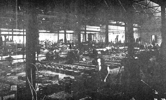
Fig. 1. A general view of the
foundry.
| The foundry, a general view of which is given in
fig. 1, comprises a large and modern building very
efficiently equipped, and which is extremely well
lighted both as regards natural and artificial
means. Moulding machines, of which numerous types
are employed, are used for practically every
operation, it having been found that castings
produced by this means are very much truer to
pattern, and on account of the uniform ramming of
the sand are made with a smaller scrap percentage
than is the case when hand methods are employed.
Both iron and non-ferrous castings are produced,
and, in addition to the ordinary sand castings, the
die-casting process is employed to a very
considerable extent, both in connection with
aluminium and also with aluminium bronze. When
melting aluminium considerable trouble is often
experienced through the corrosive action of the
molten metal on the cast iron pots used for melting.
In order to obviate this difficulty, the Sunbeam
Company coat the interior of the pots with a mixture
of ordinary water glass and whiting, it having been
found that by painting the pots daily with this
preparation they last almost indefinitely. |
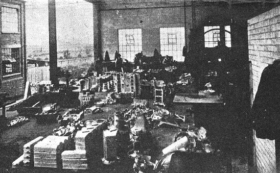
Fig. 2. The fettling shop.
|
Immediately adjacent to the
foundry is an extensive fettling section, a general
view of which is shown in fig. 2. Band saws are
provided for removing the gates or runners, and
pneumatic hammers are employed for chipping
purposes. This department is also responsible for
carrying out the necessary water-pressure tests on
cylinder blocks and cylinder head castings, etc.
As numerous jigs, special
tools, and fixtures are employed for machining
practically every component, the Sunbeam tool room
is naturally an extensive department, and in
addition to the necessary jigs and fixtures, a large
quantity of standard and special cutting tools are
made in this section.
The machine shop comprises a
modern and well equipped department, as may be seen
from fig. 3, gravity operated runways being employed
for the transportation of the heavier components
from one operation to another.
With regard to the layout of
the machines, as far as possible the shop is grouped
in various sections, each of which is completely
equipped for the efficient production of a given
component or unit. For example, fig. 3 shows the
section in which cylinder block castings are
machined. |
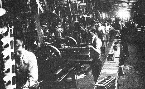
Fig. 3. A portion of the runway in
the machine shop.
|
Commencing with the rough
milling operation at one end of the line of
machines, each casting travels along and undergoes
successive operations until it reaches the far end
in a completely finished state. There is no possible
doubt that this arrangement constitutes a most
efficient production method where fairly large
quantities of parts are required, for it reduces the
necessary progress or routine staff to a minimum and
also enables the work of the operation inspectors to
be considerably facilitated.
Practically the only exception
that is made to this method of machine arrangement
in the Sunbeam works is in the case of the automatic
section, where, on account of the highly specialised
labour that is required for setting-up and operating
these machines, it is considered advisable to group
all tools of this class together. It may be
mentioned that the Sunbeam Company operates one of
the largest batteries of Potter & Johnson automatics
in this country, these machines being almost
exclusively employed for the machining of such parts
as gear blanks, brake drums, pistons, etc.
In practically every works a
certain amount of trouble arises on account of the
difficulty of distinguishing one class of steel from
another, after it has left the stores for use in the
works. A widely adopted scheme is to paint the
various grades of steel with distinctive colours in
the form of a strip an inch or so wide extending the
length of the bar. In the course of time, however,
the colours are apt to fade or rub off, and hence
confusion arises. In order to overcome difficulties
of this nature in the works under consideration, a
scheme has recently been introduced by which every
individual piece of bar stock is stamped for the
whole of its length with a distinctive description,
such, for example, as
3 per cent nickel, mild steel, etc. |
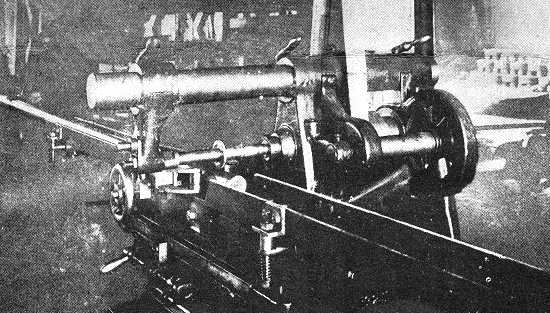
Fig. 4. Stamping bar stock.
|
Fig. 4 illustrates the device
employed for stamping the bars, from which it may be
seen that the stamp, in the form of a circu1ar disc
having the necessary lettering cut on the periphery,
is mounted on the arbor of a small horizontal
milling machine. On the worktable of the machine are
arranged two lengths of channe1 iron, forming an
approximate guide for the bar, which is actually
supported on rollers on the underside, minimising
the friction to the greatest possible extent, thus
enabling the bar to be conveyed along merely by the
rolling action of the circular stamp.
To accurately centre the bars
in relation to the circular stamp, a pair of rollers
located in the vertical plane are provided. These
are operated by a self-centring mechanism actuated
by the hand wheel to be seen in the illustration,
and are closed in on the bar, which is thus
automatically centred. The necessary degree of
pressure is obtained by raising or lowering the
worktable of the machine, and the device is designed
so that it will accommodate all sizes of bars used
in the works.
The water-cooled detachable
cylinder heads are of cast iron, and considerable
care is taken in the foundry to ensure the correct
position of the numerous cores that are necessary
for moulding. In machining, the first operation
consists of milling the lower face to provide an
efficient bearing face and location for the
subsequent operations. |
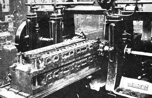
Fig. 5. Milling cylinder head
castings.
|
Next the manifold facings are
milled, and this operation is illustrated in fig. 5.
For this purpose a Hendey double spindle horizontal
milling machine is employed, the cutters being of
the inserted tooth type. As may be seen from the
illustration, four cylinder head castings are
secured in the fixture at one setting, and each
cutter serves to machine the facings of two heads as
the work is traversed past to the cutters.
A particularly simple type of
fixture is employed for balding the work, which,
briefly described, consists of a box shape casting
having two sides only. The work is firmly held in
position by substantial clamps which operate at each
end of the heads. Subsequent operations on the
cylinder heads include drilling and tapping, boring
and facing the valve guide holes and valve seats,
etc. |
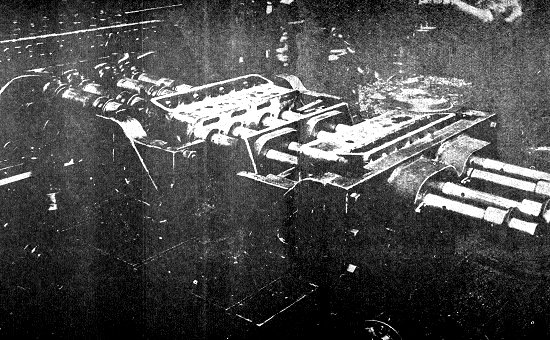
Fig. 6. Boring cylinder blocks.
|
For cylinder boring, a special machine, shown in fig. 6, is
employed, made by Messrs. George H. Alexander & Co., Ltd., of Birmingham. It
will be seen that the machine comprises a horizontal worktable of large area, on
which are mounted the necessary fixtures for locating and holding the cylinder
castings. Four spindles are provided to drive the necessary boring bars, which
are suitably supported at both ends and in between the two cylinder castings by
hardened and ground steel bushings.
It may be noted that provision is made in
the design of the boring machine to enable the centres of the boring bars to be
varied within relatively wide limits, the tool being thus
suitable for practically all sizes of cylinders. After
rough and finish boring, the cylinder blocks, which have previously been faced
on all necessary surfaces, are drilled and tapped and are finally ground in the
bores before passing to the assembly section.
For the milling of the larger aluminium components, such as
crank cases, gear
boxes, etc., multiple spindle Ingersoll milling machines of
the type shown in fig. 7 are extensively employed, The efficiency of these
machines is such that considerable care has to be taken when designing the work
holding fixtures to ensure that the actual cutting time is not exceeded by that
taken for placing the components in position.
|
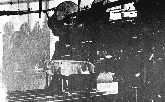
Fig. 7. Milling aluminium crankcases.
| The operation shown in progress in fig. 7 is that of
milling the upper face of a four-cylinder engine aluminium crank case. The three
cutters are of the inserted tooth type, and are in operation simultaneously, the
centre cutter facing the top of the crank case, whilst the two smaller side
cutters machine the feet. |
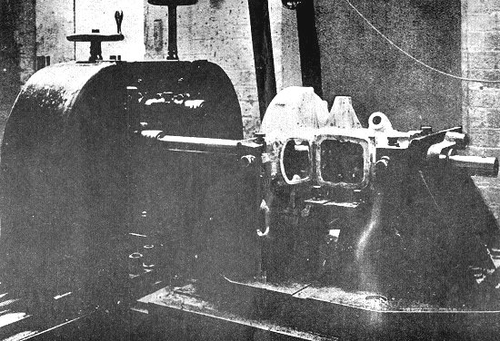
Fig. 8. Boring gear boxes.
| For boring gear boxes, the machine and equipment shown in
fig. 8 is employed, from which it will be seen that a fixture of particularly
robust proportions is used to locate the rough casting by means of a number of
adjustable stops. The machine is of the twin spindle type in order that two
boring bars may be in use simultaneously, and the fixture is constructed with
rigid supports for the bars carrying the cutters. After the boring operation has
been completed the faces machined at this setting are utilised as a positive
means of location for the subsequent operations of facing and drilling. |
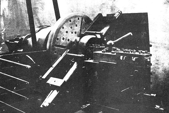
Fig. 9. Boring and facing rear axle
casings.
|
Sunbeam rear axle casings are produced from steel forgings,
and after the ends of the forgings have been machined in a lathe, the centre
portion is bored and faced by the use of a large centre lathe, provided with
special equipment of the type shown in fig. 9. It will be seen that to the
faceplate of the lathe are secured two angle plate fixtures, which are fitted
with hinged caps that serve to hold the work firmly in place.
Location of the
forging is effected by the use of a positive stop operated at one end of the
forging, as may be clearly seen in the lower portion of the illustration, whilst
one fixed and one adjustable stop make contact with the underside of the centre
circular portion of the axle casing and serve to effect radial location. Two
studs on either side of the centre of the casing carry swinging clamps, and
serve to hold the forging firmly down against the stops, thus preventing either
distortion or chatter whilst the machining operation is actually in progress.
It
will be observed that special multiple tool posts are employed so that in the
first place both flanges of the work are rough and finished bored at one passage
of the boring head, while finally both flanges are faced to width simultaneously
by use of the four tools held in the second post, which are seen in the
illustration.
Considerable use is made in the Sunbeam works of the
continuous rotary method of milling of the parts required for the product. There
is no doubt that where sufficient quantities of parts are required, this scheme
offers the most economical method of production that it is possible to devise,
but where only small batches of work are put through at a time, the natural
complexity and consequent expense of the necessary work holding fixture, renders
this method somewhat uneconomical.
|
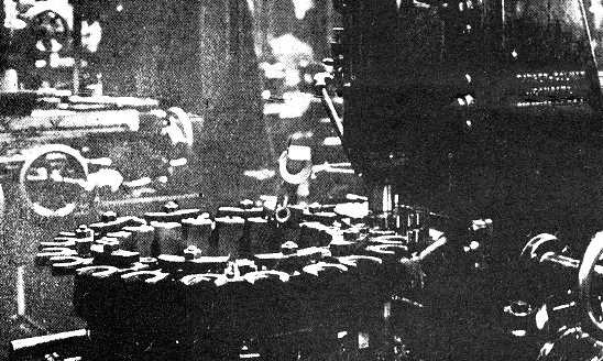
Fig. 10. The continuous milling of
change gear forks.
| Both Barber & Colman and Becker vertical machines are used
in connection with the continuous rotary milling process, and in fig. 10 is
shown a machine of the first make set up for facing change gear forks. It will
be seen that the bosses of the components have previously been bored and faced,
and thus a convenient and efficient method of location is provided. The jig
employed, comprises a cast-iron ring on the inside of which are provided a
number of hardened and ground steel plugs, which fit the bore of the
change-speed forks. A series of clamps serve to hold the castings firmly in
position, each clamp operating on two forks simultaneously. Two side and face
cutters are employed, being set to the correct width by means of washers, and it
may be observed that an extra support is provided to the cutter arbor to prevent
any possibility of distortion or springing of the cutter arbor. |
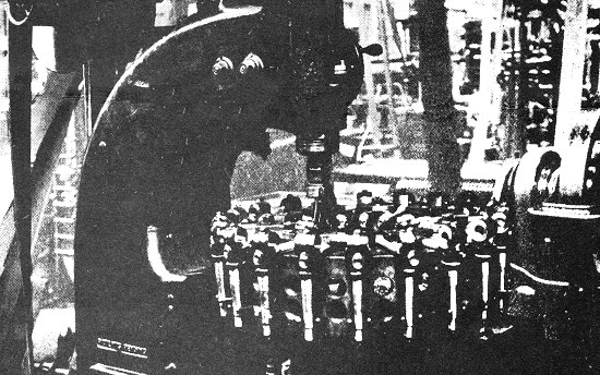
Fig. 11. Milling stub axles.
| A further operation of a somewhat similar nature is shown
in fig. 11, in this case the machine used being a Becker. The parts being
machined are stub axles which have previously been turned, bored, and faced, and
which at this operation require a series of flats to be milled on the shorter
shank.
The construction of the work holding fixture is much the same as that
shown in fig. 10, the work in this instance being located in suitable vees
formed on the upper face of the jig casting, while a number of pins which come
into contact with the longer shank of the work towards the bottom extremities
serve to control the radial setting. In addition to numerous modern and standard types of
adjustable multiple spindle drilling machines, special heads of this type are
extensively used for drilling a number of components. |
|
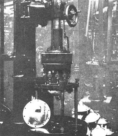
Fig. 12. A special
multiple spindle drill head. |
Fig. 12 illustrates the head
and fixture employed for the drilling of rear axle
casing covers.
Each drill
spindle, together with the main driving shaft of the attachment, is carried on
substantial ball bearings, the whole of the gearing being enclosed by a suitable
safety guard.
It will be seen that a particularly simple type of work holding
fixture is employed, suitably supported on four pillars or legs raising the work
to a convenient height, and in order that the same fixture may be employed for
drilling other similar parts, which are somewhat longer than those shown. |
| In fig. 13 is shown a simple yet efficient type of nut
castellating machine comprising a cutter spindle which carries the necessary
slitting cutter for producing the slots.
The cutter spindle is connected by means of
reduction gearing to a shaft carrying a pair of
circular plates that are provided with numerous
serrations on the inside faces in order to locate
and firmly grip the nuts being castellated.
A third disc located between the two gripping
discs serves to provide a positive means of locating
the nuts so that the slots shall be the correct
depth. |
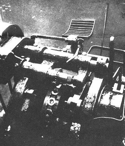
Fig. 13. An efficient nut
castellating machine. |
|
The shafts on which the gripping plates
are mounted are arranged so that their axes are at a slight angle, and when the
nuts are travelling past the cutter they are firmly gripped on account of the
plates being closer together at this point. Immediately a nut has passed the
cutter the plates begin to open, and after a short travel the nuts automatically
drop free of the fixture. As the empty spaces again rotate towards the cutter,
an operator standing in a convenient position places further nuts in position,
and thus the operation is entirely continuous.
To prevent any spring of the gripping plates, two rollers
are provided, which may be seen in the illustration immediately under the cutter
arbor, and these serve to hold the circular plates or discs firmly in position,
and to rigidly grip the nuts.
Great care is taken in the assembly of the various units
that comprise the Sunbeam chassis, and individual tests are carried out in
connection with each engine, gear box, rear axle, etc.
|
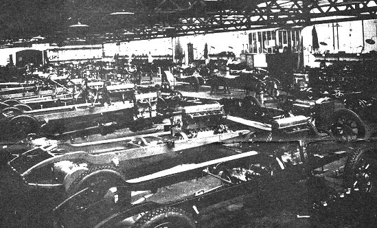
Fig. 14. A general view of the final
assembly shop.
|
A particularly extensive
department is devoted to the final assembly operations, and a general view of
this section is shown in fig. 14. After leaving the assembly shop the completed
chassis undergoes further exhaustive tests on the road, and when these have been
satisfactorily passed, the chassis is handed to the coach building department for
body fitting, painting, etc.
In conclusion it may be mentioned that the standard of
workmanship and procedure generally in the Sunbeam shops is of particularly high
quality.
|
 |
Return to
the
previous page |
|