| Introduction
Modern towns and cities rapidly grew during the
Victorian period when large numbers of people flocked
there to find work in the many factories and industries
that were appearing at the time. This resulted in
numerous problems including cramped living conditions
that were often unsanitary.
The industrious Victorians found
solutions to the problems and in doing so laid down the
basis of modern town and city life, which is dependant
upon many essential services such as gas and electricity
supplies, refuse and sewage disposal, an adequate
transport infrastructure and street lighting, schools,
hospitals, and last but very far from least, a clean and
reliable water supply.
The serious health problems that
can arise from an unclean and inadequate water supply
caused many deaths in the 19th century. Large
numbers of people died as a result of the cholera
epidemics that occurred in 1831 to 32, 1848 to 49, 1853
to 54, and 1865 to 66. The disease spread from India and
became known as Asiatic Cholera. It spread via trade
routes and reached Europe in 1826, spreading from Turkey
to Russia, Poland, Germany and the Baltic ports, from
where it came to Sunderland in 1831. In January 1832 it
arrived in Newcastle and Gateshead and soon reached
York, Leeds, Manchester, the Black Country, London, and
reached Devon and Cornwall during the autumn.
In Bilston there were 745 deaths
and from 50 to 200 deaths in each of the other Black
Country towns. In London there were 4,218 deaths.
Thankfully by the end of 1832 the epidemic had ended.
The disease returned in 1848 and again lasted for around
two years. This time there twice as many deaths.
When the disease returned in 1853
people began to realise that it had something to do with
the unclean water supply, although the exact cause was
not initially understood. As before there were many
deaths in London, and after the "Great Stink" of 1858
when the River Thames smelled of raw sewage, something
was finally done. During the next 7 years Joseph
Bazalgette and the Metropolitan Board of Works
constructed London’s immense system of sewers, which led
to a clean water supply and the eradication of the
disease. It was then accepted that cholera was spread by
a water-borne bacteria, and the importance of a clean
water supply became apparent.
|
|
Throughout the country local
authorities built water works and these were greatly
improved to provide a plentiful supply of clean water.
Wolverhampton was typical in this respect and greatly
benefited from the work of the local authority's water
committee, whose members worked tirelessly to provide an
essential and adequate supply of clean water. This
greatly improved people's lives and helped to reduce the
amount of disease, and the resulting death rate.
One of the important figures on the
committee was its chairman John Marston, better known as
the manufacturer of Sunbeam bicycles, motorcycles and
cars.
By a strange coincidence, one of
his homes, The Oaks in Merridale Road was purchased by
the water company in the early 1950s and became the
company's office. Partly thanks to his work the town
eventually received the high quality water supply that
it needed. |
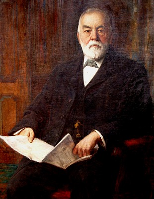
| John Marston in
his later years. Courtesy of the Marston
Wolverhampton Heritage Trust. |
|
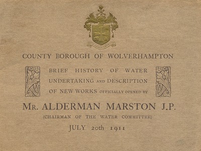
| To commemorate the committee's achievements a small
booklet was published in 1911 describing the development
of the water works. The booklet, which provides a
detailed description of the works can be read below. |
|
A Brief History of Water
Undertaking and Description of New Works Officially
opened by Alderman John Marston J.P. Chairman of the
Water Committee. 20th July, 1911
 |
|
In the year 1845 a small company
was formed under the style or title of "The
Wolverhampton Waterworks Company" which sought and
obtained parliamentary powers to sink wells and
establish works at Tettenhall, for the purpose of
supplying water to the town and suburbs of
Wolverhampton.
The scheme of the company was
strongly opposed in Parliament by the proprietors of the
Staffordshire and Worcestershire Canal, who feared that
if wells were sunk below the level of their Canal and
extensive pumping operations were undertaken, their
waterway would be prejudicially affected, and as the
result of their opposition the depth of the wells was
limited to 18 feet below the level of the Canal at
Newbridge.
The effect of this limitation
practically ruined the scheme, for upon its completion
the company found that they could only obtain about
150,000 gallons of water per day instead of the million
gallons for which works had been constructed.
The Cornish "Bull" engines which
were installed were designed by one of the most
celebrated engineers of the day, Thomas Wickstead, and
their duty was to raise the water from the wells and
force it over a stand pipe fixed inside the structure
which is now used as the smoke stack. |
|
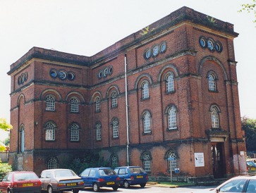
Tettenhall waterworks. |
The comparatively small quantity of water obtained
was inadequate for the needs of the district and the
company decided to apply for further powers and in 1851
powers were obtained to sink wells and establish works
at Goldthorn Hill, but the second scheme of the company
proved more costly and even more disappointing than the
first, for the new wells only yielded an additional
supply of 120,000 gallons per day of very hard water. |
|
Anticipating an abundant yield from
their new wells and headings the company had installed a
large Cornish beam engine and constructed two covered
reservoirs to hold 750,000 gallons each, but the small
yield of the new works was not commensurate with the
expenditure incurred, and it utterly failed to satisfy
the requirements of the district, consequently the
company was again forced to seek additional
parliamentary powers, and in 1855 embarked upon its
third and last venture. In the same year the
Wolverhampton Corporation and a new company styled "The
Wolverhampton New Waterworks Company" promoted bills in
opposition to the original company, and a three-cornered
fight ensued for powers to construct a pumping station
at or near Cosford Bridge, and to impound the upper
waters of the River Worfe.
The bills of the original company
and the Corporation were thrown out and the scheme of
the new waterworks company was sanctioned by Parliament,
and the following year the new company obtained another
Act for the transfer of the properties and rights of the
original company.
With the acquisition of the old
works, the new company appears to have revised its
scheme, for instead of constructing reservoirs to
impound the upper waters of the River Worfe, the river
course was slightly widened and a dam or weir
constructed in conjunction with the authorised pumping
station at Cosford Bridge, and considerable alterations
and extensions were made to the works of the old
company.
At Cosford the works undertaken by
the new company involved the construction and erection
of engine and boiler houses, chimney, two rotative
Cornish engines, boilers, and a pumping main was laid to
Tettenhall, and, in order to supplement the yield of the
River Worfe during dry seasons, a borehole was sunk and
the water therefrom was conveyed into a brick tank where
it mixed with the river water.
At Tettenhall the works were
extended, the erection of a new engine and boiler house
(the old boiler house and smoke stack being demolished
to enable this work to be carried out), a reservoir was
constructed for the storage of the Cosford water; one of
the old well engines was altered into a forcing engine,
and the Goldthorn Hill well engine was taken down,
altered, and re-erected in the new engine house as a
forcing engine to deal with the Cosford water; new
boilers were installed; the stand pipe was taken down
and the brick shaft in which it was encased was
converted into the smoke stack. |
| At Goldthorn Hill a small engine was erected in the
place of the large Cornish well engine; a supply tank
was erected on the top of the engine house the town
mains were extended to the reservoirs and by this means
the reservoirs were converted into balancing tanks to
govern the pressure in the town mains. |
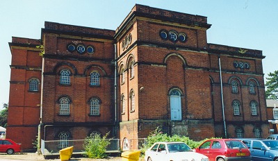
Another view of the works at
Tettenhall. |
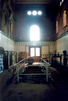
The wonderful interior of the
waterworks at Tettenhall. A cathedral to water, and
steam pumping engines. |
These works took several years to carry out, but
sufficiently good progress was made to enable the
company to supply Cosford water into Wolverhampton
during October, 1858. A few years later the
Corporation made provisional arrangements with the
waterworks company for the acquisition of their
undertaking, and in 1861 the undertaking was acquired by
the Corporation under the powers of the "Wolverhampton
Waterworks Transfer Act" and on the 1st January, 1868,
the Corporation entered into possession of the works;
the conditions of transfer being that the Corporation
should, after a certain date, pay in perpetuity 5 per
cent. upon the Preference Shares, and 4 per cent. upon
the Ordinary Shares of the company.
Upon obtaining control of the undertaking it became
necessary for the Corporation to obtain powers to
continue, maintain, alter and improve the existing
waterworks, and the requisite powers were subsequently
obtained by the Wolverhampton Improvement Act, 1869. |
|
The yield of the various works
proved adequate for the demands of the district until
1874, when a very dry summer caused a shortage in the
river supply, and the Corporation then sought advice as
to the possibilities of obtaining an increased yield
from underground sources by carrying out further sinking
operations at Cosford. The late Mr. J. F. Bateman was
consulted and he recommended the Corporation to sink a
deep borehole, and acting upon the advice given, the
Corporation sunk a large diameter borehole 918¾ feet
deep. This work was commenced in May, 1876, and
completed in December, 1877, and upon completion the
borehole yield by artesian force, a very large
additional quantity of water of most satisfactory
character. A few years later, however, the increasing
demands of the district caused the Corporation to again
seek an additional supply, and upon the advice of the
Consulting Engineer,
Mr. H. J. Marten it was decided to
extend the Cosford Works by sinking a well in close
proximity to the deep borehole and to connect the well
and borehole together by a heading so that an increased
yield from the underground sources could be obtained by
pumping down below the normal water level in the
sandstone formation. The well was commenced in 1881 and
the following year it was completed, and the large
Cornish engine which was then erected by the Lilleshall
Company, speedily proved the wisdom of the course
adopted.
It then became necessary to augment
the pumping plant at Tettenhall to deal with the
increased yield of the Cosford Works and to provide for
the growing demands of consumers, and in 1884 another
house was erected, and a large Cornish forcing engine
was installed by Messrs. Hathorn, Davey & Co. of Leeds.
The next step the Corporation
deemed it advisable to take was the duplication of part
of their system to prevent the possibility of shortage
of supply through breakdowns of engines at Cosford, or
the bursting of the pumping main, and in 1888 operations
were commenced which took several years to complete, and
entailed a variety of work being undertaken. |
| An additional pumping main was laid from Cosford to
the summit of Summerhouse Hill; another well was sunk at
Cosford; the buildings were extended and two more
engines were installed by Messrs. Hathorn, Davey & Co.,
one engine as reserve to the Lilleshall well engine, and
the other as a reserve to the original forcing engines.
About the time this work was nearing completion the
Corporation consented to release the Bilston.
Commissioners from their agreement to purchase water in
bulk, although the works were then quite capable of
yielding sufficient water for the needs of the entire
district, but one reason which influenced the decision
was the prospect of largely increasing demands and
consequently the necessity for incurring further capital
expenditure upon entirely new works, and it was pointed
out that the severance of Bilston from the water area
would immediately relieve the Corporation of the demands
of a population estimated to exceed 20,000; the margin
of supply over demand would be largely increased and the
question of providing additional works could be
postponed. |
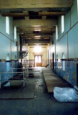
Another interior view of the old
waterworks. |
|
From a financial point of view the
action of the Corporation in thus disposing of part of
the water area was undoubtedly a mistake, but from the
point of view of conserving the supply, it must be
admitted the anticipations of the advisers of the
Corporation as to the capability of the works to
maintain a constant supply of water to the district for
a number of years, have been fully confirmed, for beyond
improving the general conditions at the Pumping Stations
and extending the distribution mains for the continued
growth of consumers, the auxiliary works officially
opened today represent the only actual additional supply
works since undertaken. It should be mentioned, however,
that an abortive attempt was made in the year 1896 to
obtain an additional supply from the neighbourhood of
Lower Penn; that unsuccessful applications were made to
Parliament in 1901 and 1902, for power to construct
works near Worfield, and that it was not until the
Corporation succeeded in arranging terms with the
proprietors of the Staffordshire and Worcestershire
Canal Company (which Parliament confirmed in 1903), that
the sinking of deep wells or boreholes at the Tettenhall
station was made possible.
The present Waterworks Engineer is
responsible for the scheme of extension at this station
and for the design and construction of the various works
incidental thereto, which have involved the sinking of
three boreholes; the erection of an Engine House; the
construction of a triple expansion rotative pumping
engine; the construction of an additional storage
reservoir, and the laying of a 24-inch pumping main to
Goldthorn Hill. |
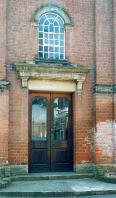
The ornate entrance to the old
building at Tettenhall. |
The boreholes were sunk by Messrs.
A. C. Potter & Co., of Lant St., Borough, S.E., in the
most expeditious manner. In the first place a trial
borehole was sunk 1,001.75 feet deep by means of which
the formations were proved and the quality and
approximate quantity of water available was ascertained,
and it is due to the success of this boring that the
other works were then undertaken.
The trial borehole is 16ins.
diameter from the surface to 300 feet deep; 12ins. from
300 to 632 feet; 10½ins. from 632 to 929 feet, and 9ins.
From 929 to 1,001.75 feet.
The permanent or pump boreholes are
1,100 feet deep, and their diameters are as under:-
28ins. from the surface to 300 feet deep; 24ins. from
300 to 450 feet; 20ins. from 450 to 830 feet; 16ins.
from 830 to 930 feet, and 14ins. from 930 to 1,100 feet. |
|
From the surface to 300 feet, each
borehole is lined with steel tubes; those in the trial
borehole being 15ins. internal diameter, and those in
the permanent boreholes 25ins. internal diameter.
Specially designed shoes with lead pipe and india rubber
compression rings, are fitted at the bottom of each set
of tubes by means of which tight joints are made with
the walls of the boreholes, but before proceeding with
other work the effectiveness of the shoes was thoroughly
tested and then the spaces between the tubes and
borehole walls were filled with cement grout to prevent
any possibility of surface water finding its way into
the boreholes. From 830 to 930 feet the boreholes are
lined with perforated tubes to prevent the pebbles and
the faulty sandstone there met with, from falling in and
choking up the holes.
As the work progressed samples of
water were taken and submitted to the Borough Analyst,
Mr. E. W. T. Jones for examination, and the following is
a copy of his report upon a sample he obtained at the
works on the 22nd January last. |
| |
Grains per gallon |
| Total Solid Matter dried at
212 deg. Fah. |
21.0 |
| Free and Saline Ammonia.
|
0.000 |
| Albuminoid Ammonia |
0.000 |
| Nitric Nitrogen |
0.05 |
| Combined Chlorine |
0.98 |
| Oxygen absorbed in 4 hours at
80 deg. Fah. |
0.000 |
| Colour through 2 feet |
very pale bluish-green
tinge |
| Appearance |
Clear |
| Hardness before boiling |
14.28 |
| Ditto after ditto |
5.50 |
| Ditto Temporary |
9.78 |
|
Bacteriological Examination:
No organisms were shown on Gelatine
at 20 deg. C., nor on agar-agar at 37 deg. C. after 4
days incubation.
|
| The Solid
Matter in solution consisted of: |
| Lime |
7.70 |
| Magnesia |
1.71 |
| Soda |
1.11 |
| Potash |
0.51 |
| Sulphuric
Anhydride |
0.38 |
| Nitric Anhydride |
0.19 |
| Chlorine |
0.98 |
| Silica |
0.77 |
| Carbonic Anhydride |
7.87 |
21.22 |
| Less Oxygen for
Chlorine |
|
0.22 |
|
|
Total |
21.00 |
|
From this it will be seen that although the water is
a shade harder than the water hitherto supplied, it
is an excellent water for a town supply, in fact,
organically and bacteriologically it is perfect.
The engine which has been
erected to deal with this water is a vertical triple
expansion rotative condensing engine of the inverted
type with the rams or force pumps placed directly
under the steam cylinders and connected to cranks
set at angles of 120 degrees, and with the borehole
or lifting pumps operated from the ends of the main
shaft.
It is capable of lifting 62,500
gallons per hour with the borehole pump from any
depth not exceeding 260 feet below the floor level
and delivering the same into a suction tank, whilst
the rams are capable of forcing 125,000 gallons per
hour against a head of 180 feet when running at a
piston speed of 160 feet per minute. Steam for the
engine is obtainable from the boilers which replaced
the old ones a few years ago, and the working
pressure will be 160 lbs. on the square inch.
The general arrangement is such
that the engine can be worked either as a ram pump
only, or as a lifting engine only, but in ordinary
work it will perform both duties, and then it will
pump equal proportions of Cosford and Tettenhall
water into the distributing mains.
|
| The leading
dimensions of the engine are as under, viz.:- |
| Stroke 3ft.
6in.: |
|
| High Pressure
Cylinder |
19in. diameter |
| Intermediate
Cylinder |
29½in. diameter |
| Low Pressure
Cylinder |
46in. diameter |
| Ram Pumps |
16in. diameter |
| Stroke 2ft.
9in.: |
|
| Borehole Pumps |
16in. diameter |
The flywheels are 12 feet diameter and weigh about 11
tons each. The valve gearing is of the well known
Corliss type end is operated by eccentrics on the main
shaft. The contract for the engine was placed in the
hands of Messrs. Galloways Ltd., of Manchester.
|
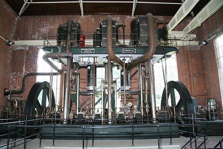
An impression of how the interior
of Tettenhall waterworks must have once looked when its
Galloway's engine was there.
The photograph shows the preserved
Galloway inverted vertical triple expansion pumping
engine at Maple Brook Pumping Station. Courtesy of
Chris Allen. |
|
The engine house is 48 feet long by
22 feet wide and 52 feet high, measured from the
basement floor to the shoes of the roof principals, and
its situation is between the boilers and the engine
house which was erected by the new waterworks company
about the year 1860, sufficient space having been left a
few years ago, when substituting new boilers, for the
purpose thereof.
The foundation portion of the house
had to be carried out by piece work as parts of the
boiler house had to be demolished; boiler and other
foundations had to be taken out; the main flue had to be
diverted and rebuilt, and provision made for safely
continuing pumping operations, and this work was
executed by Mr. H. Holloway, of Bilston Road,
Wolverhampton, but the contract for the superstructure
of the house was placed in the hands of Messrs. Willcock
& Co., of Darlington Street, Wolverhampton.
The additional storage reservoir
has been formed partly by excavation and partly by
embankment. It has been constructed throughout with
cement concrete, in the proportions of four parts by
measure of broken Bentley stone and two of sand to one
of cement, and the whole of the concrete was
mechanically mixed.
| The
principal dimensions of the reservoir are as
under, viz.:- |
| At
coping of walls |
312ft. long by 202ft. wide |
| At
floor level |
299ft. long by 189ft. wide |
|
Thickness of wall at top |
1ft. 6in. |
|
Thickness of wall at floor |
8ft. 0in. |
| Depth
from coping to floor |
19ft. 0in. |
|
Capacity at normal working level (16 feet) |
6,000,000 |
|
Surface area of water at working level |
1.396 acres |
The inlet main is laid along the
embankment, and is controlled by a Venturi meter. The
outlet main is connected to the outlet main of the old
reservoir, so that in ordinary work the water level in
both reservoirs can be uniformly maintained; but a
branch main is laid from the outlet main to the suction
tank of the new engine, and the arrangement of the mains
is such that all the engines at the station can be fed
with water from either or both reservoirs. The
connections to the old mains were all made under
pressure by means of one of Ruscoe's patent machines.
The object of the new reservoir is
not intended for increasing storage accommodation, but
its provision was felt to be necessary to enable the old
reservoir to be emptied, cleaned and repaired. The
contract for this work was placed in the hands of Mr. H.
Holloway, of Bilston Road, Wolverhampton.
The work of laying the 24inch
pumping main from Tettenhall to Goldthorn Hill was also
entrusted to Mr. Holloway, and with the exception of the
portion over the Smestow Brook and the canal at Compton,
it is composed of cast-iron socket and spigot pipes. The
portion over the brook and canal at Compton is of mild
steel with flanges welded on, each length of which has
been specially made to meet the peculiar conditions
which existed.
The pipes generally used are 12
feet in length, and weigh approximately 1 ton 9 cwt.
each. They are jointed together in the following way,
viz.-
| A ring of ⅜in. round lead rod was first
forced to the back of the socket, then lead
wool was inserted and caulked in layer by
layer to within 3¾ inches of each socket
face. Plain hemp was then caulked in to
within 1¾ inches of the socket face, and
finally the remainder of the socket was
filled with lead wool, each skein of which
was thoroughly caulked in. |
The pipes were made by the Stanton
Iron Works Co., and they were all subjected to a test
pressure of 260 lbs. on the square inch before leaving
the works. The main is divided into sections controlled
by stop valves and provided, where necessary, with air,
reflux, bypass and emptying valves, all of which valves
were supplied by the Glenfield Co., of Kilmarnock.
A comparison may now be made of the
conditions existing today with those at the time of the
transfer of the undertaking to the Corporation. In 1868
the works were incapable of distributing more than
2,000,000 gallons per day whilst the demand averaged
1,500,000 gallons; 12,890 houses were connected to the
mains and the income from water sales amounted to
£12,943.
Today the works are capable of
distributing over 5,000,000 gallons per day, whilst the
demand during the year ending March 31st, 1911, averaged
3,474,000 gallons; 35,415 houses were connected to the
mains at the same date, and the income from water sales
amounted to £37,553.
At the transfer the actual
expenditure upon works and plant amounted to £210,327.
10s. 0d., and at March 31st, 1911, the Capital actually
expended amounted to £392,562, of which sum £93,567 had
been paid off.
In concluding this brief account of
the undertaking a reference may be permitted to those
responsible for its present satisfactory position. From
1868 to 1881, Mr. Alderman Fowler (subsequently first
Viscount Wolverhampton) presided over the Water
Committee, and the fact must again be recorded that it
was principally due to his initiative that the
undertaking was acquired by the Corporation; from 1881
to 1891 Mr. Alderman J. G. Wright held the office of
Chairman, and since 1891 to the present date, Mr.
Alderman Marston has presided over its destinies.
From 1868 to 1892 the management of
the works was entrusted to Mr. Lyons Wright, who
formerly held the position of secretary to the
waterworks co., and since July, 1892, the present
Engineer, Mr. E. A. B. Woodward has managed the
undertaking, and been responsible for the design and
carrying out of the various additions and alterations
which have been made to it since his appointment, and
the date hereof, July 20th, 1911. |
 |
Return to
the
previous page |
|