|
When the E.C.C.'s construction work was almost
complete, a running trial and inspection of the whole line was
undertaken on 13th January, 1893. This was reported in the
Manchester Weekly Times as follows:
|
On Saturday a running trial and inspection was
made along the whole length of the new line. The railway took over
three years to construct and cost £85,000 per mile. Lord Salisbury
will visit Liverpool on the 4th February to officially
open the line which runs from Herculaneum Dock to Rimrose Wall,
Seaforth, a distance of six miles. It uses standard gauge track and
there are thirteen stations with another due to be erected at
Seaforth.
Mr. Thomas Parker of Wolverhampton has designed
and carried out all of the electrical work in the electricity
department for the Electric Construction Corporation Limited. That
Corporation is under an agreement to put-down and maintain engines,
boilers, electric lights, conductors, signals, carriages, switches,
and indeed all appliances, and takes the responsibility of the
successful running of the concern for two years, guaranteeing the
proprietary company to the extent of 3.5 pence per train mile run.
The agreement covers depreciation, repairs and several expenses, and
indeed amounts to a bond to take over everything but the actual
management and collecting of fares. Mr. Parker estimates that at a
cost of 2 pounds of coal, a train of two carriages weighing 40 tons,
when each filled with 56 passengers, can be carried one mile.
At the Bramley-Moore Dock Depot there are four horizontal
compound engines by Messrs. Musgrave, of Bolton, each
driving a separate Elwell-Parker dynamo of powerful energy,
and capable of jointly working up to 2,000 horse power. The
boilers are fitted with mechanical stokers, and there is an
arrangement of mechanical coal brokers by which all handling
is entirely obviated, the coal being dropped into them from
the high-level coal railway. From the dynamos the
electricity generated is by means of copper conductors
carried through switch arrangements into the railroad,
instruments in the shed indicating the electrical pressure
upon the road and passing thereto.
The copper conductors are connected to the outside rail
and with a central conductor between the rails in each set,
the positive and negative sides of the circuit being thus
formed. Hinged conductors of cast iron, sliding upon this
conductor make the connection between the motors upon the
train and the dynamos at the generating station. The motors
are carried by the passenger carriages, and the quantity of
electrical energy picked up can be regulated by the man in
charge of the train. The same principal is seen in the case
of the Blackpool tramway, only for obvious reasons the
conductor at Blackpool is below ground, whilst in the
present instance it is on the permanent way, and has the
appearance of a third rail. The conductor is made of mild
steel and its dimensions are about four inches square.
Although two carriages form a train, these vehicles are so made that
any number can be coupled together. They are so coupled as to give a
motor at each end of the train, and the motors are connected so as
to be controlled from either end by the driver, who will always
travel in front, changing ends upon arrival at the terminus, and
carrying with him a key, without which the motors cannot be
operated. Students of electrical science will understand by which
law it is impossible for these trains to travel more than 35 miles
an hour. Mr. Parker says that the moment that very respectable speed
is reached, the motors, instead of picking up electrical power from
the conductors, would at once begin to return power back to the
dynamos. The trains make the journey in 29 minutes including the
stopping times at the stations.
The inspecting party left Water Street Station
shortly after half past one and completed their task in a couple of
hours. During the run the train reached a speed of 30 miles an hour.
The weather that day was awful and the party were pleased to see
that the trains could operate normally under such conditions.
The party included Mr. T. Snape, M.P., Sir W. B.
Forwood, Mr. George Melly, Mr. J. Barrow, Mr. D. Meldrum (Cheshire
Lines Committee), MR. C. A. Rowlandson, Mr. Reginald Todd, Mr. Evanson, Mr. H. J. Brodie, Mr. A. Bare, Mr. P. Higginson, Mr. Thomas
Parker, Mr. S. B. Cottrell (General Manager and Resident Engineer),
Captain Wilkinson, and Alderman Miles and Broughton, of Bolton. In
the evening Mr. Parker entertained the party at the Adelphi Hotel.
|
|
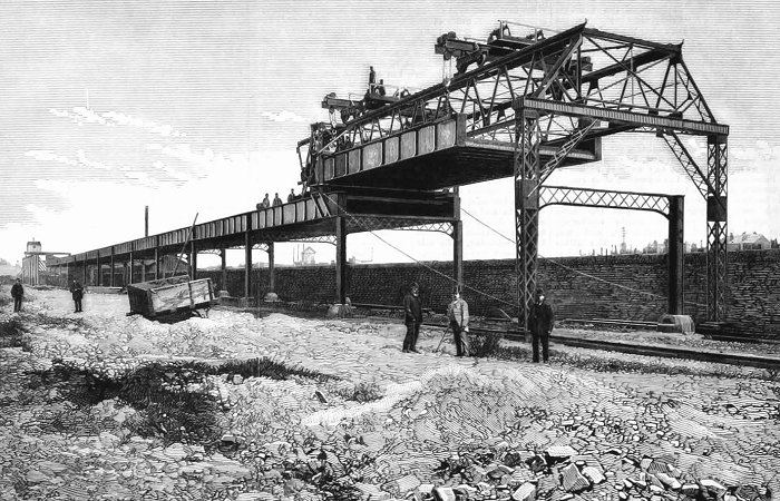
The railway during construction. From The
Engineer.
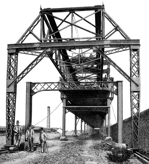
Another view of the construction. From The
Engineer.
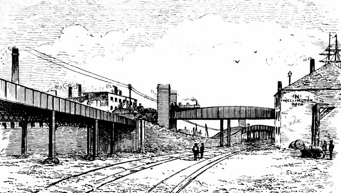
The dip under the Lancashire & Yorkshire
Railway. From The Engineer.
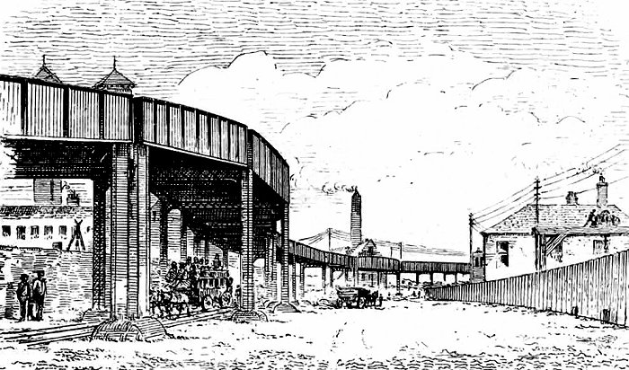
The double curve near the Alexandra Dock. From
The Engineer.
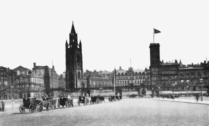
The overhead railway, as seen from the pier
head. From The Engineer.
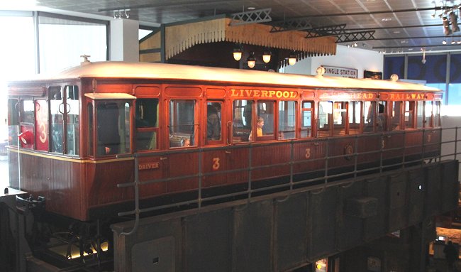
The preserved third class motor coach in the
Museum of Liverpool.
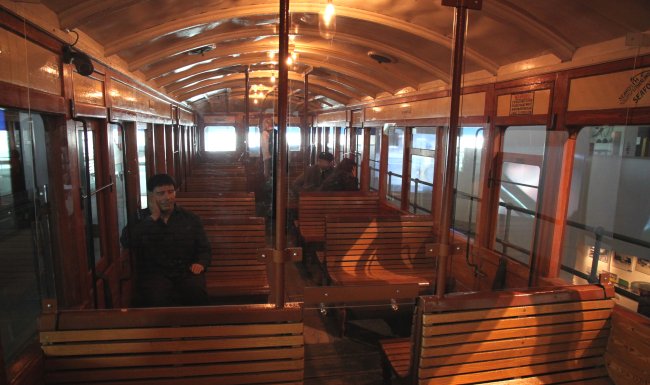
The interior of the preserved motor coach.
 |
|
 |
|
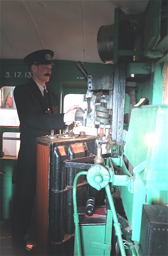
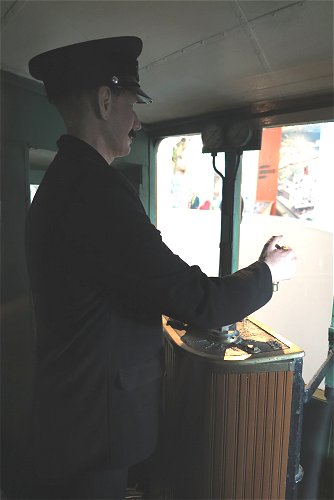
The driver's
compartment in the preserved motor coach. |
The railway was formally opened by the Marquis of
Salisbury on Saturday, 4th February, 1893. This was recorded in the
following Monday's edition of the Liverpool Mercury, as follows:
|
Opening of the Liverpool Overhead Railway
Liverpool is the first city in England to build
an overhead railway, and the first city in the world to adopt
electricity as a means of working such a railway, and on Saturday
last, the formality of opening this unique undertaking was performed
by the Marquis of Salisbury. It could hardly be possible to imagine
a fitter person than the ex-premier for performing such a ceremony,
as he has the reputation of being an enthusiastic student of
electricity, and, in addition to that, is one of the two
distinguished men to whom for the last twelve years the country has
alternately trusted its government.
The party arrived at Bramley-Moore Dock and
entered the generating station, which is built in the arches that
support the Lancashire and Yorkshire Railway. All of the vessels in
the dock and the surrounding streets were bedecked with bunting, the
weather was bright, and the scene was of the gayest description, as
equipages and cabs, the picturesque uniforms of the mounted police,
the general animation, the large bodies of police under their
inspectors, lent no small affect to the ensemble.
The Marquis was accompanied into the generating
station by Sir. W. B. Forwood, the Chairman of the Overhead Railway
Company, the Mayor, Mr. R. D. Holt, Lord Lathom, Mr. A. B. Forwood,
M.P., Mr. Brancker, Chairman of the Dock Board, Sir Daniel Cooper,
Chairman of the Electric Construction Corporation, the Rev. Canon
Armour, Mr. J. B. Smith, Mr. E. Laurence, Chairman of the Gas
Company, and others. Also present at the inaugural ceremony where J. A. F. Aspinall (Lancashire and Yorkshire Railway), and Thomas
Parker. The station had been arranged for the accommodation of a
large number of visitors, and that, although there was no
overcrowding, the available space was filled.
The party ascended a platform, speeches were made
and the presentation of a small silver inkstand was made to Lord
Salisbury, who started the electric current of 2,000 horse power
which magically draws the trains over the lines. When the ceremony
was over the party accompanied Lord Salisbury to Sandon Station
where a specially decorated train was waiting to convey them on the
first official trip on the line. The remainder of the party
travelled to Clarence Dock Station where two trains were waiting to
take them over the same route.
With regard to comfort of the new style of
locomotion, it may be said that it is delightful travelling. A
handle is turned, and without any visible means of propulsion or
attraction, off go the carriages with a smooth and even motion,
which can be regulated at the will of the engineer. The carriages
are built on the American principle, with a central passage open end
to end, with seats back to back transversely. The sides are nearly
all window, thus affording an excellent view of the long stretch of
docks. The sensation going down the “switch-back”, necessitated by
the fact that the overhead railway has to go beneath the high level
railway bridge at the Bramley-Moore Dock, is strongly remindful of
the form of amusement which was so popular a year or two ago, though
in a very much more modified degree, the speed of the train
retaining almost uniform regularity. Just beyond the Sandon Station
the marquis’s train was seen coming from the Alexandra Dock,
preceded by flashes of electricity, thus showing the actual power
which moves the carriages.
The train arrived at the Alexandra Dock Station,
with admirable celerity the carriages were moved over the points to
the down line and a swift journey was made to the Water Street
Station, where the passengers disembarked after a most enjoyable
trip. His lordship, however, was taken on to the Custom House
Station, whence he was driven to the Town Hall where a luncheon was
given by the Mayor.
|
|
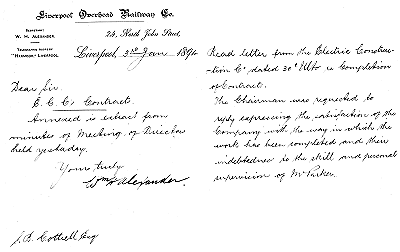
The railway company were obviously delighted with
the E.C.C.'s contribution to the railway, as can be seen from the
following letter, in which the company is relieved of its obligation
to oversee the running of the line. It also is proof of Thomas
Parker's undoubted skills as a first class engineer and his great
skill in project management
 |
|
The letter received
from the railway company. |
The letter reads as follows:
|
The Liverpool Overhead Railway Company
31 James Street
Liverpool
6th January, 1894
To the secretary of the Electric Construction
Company.
Dear Sir,
I am desired by my colleagues to express to you
their satisfaction with the manner in which your company has
fulfilled its contract for the electrical equipment of this railway.
The machinery has been well and substantially
made, it is economical in working, and its efficiency may be gauged
by the fact that during the ten months the line has been opened we
have run a five minutes’ service of trains, and 96 percent have been
on time.
We are now able to relieve you of the charge of
our generating station, which we consider has proved its capacity
and reliability.
We feel that these excellent results are very
largely due to the scientific skill, thought, and untiring industry
of your works director, Mr. Parker, to whom we ask you to kindly
convey our thanks.
I am faithfully yours, William B. Forwood,
Chairman.
|
|
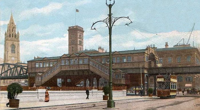
The overhead railway. From an old
postcard.
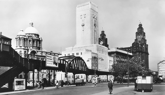
Another view of the railway, also from an old
postcard.
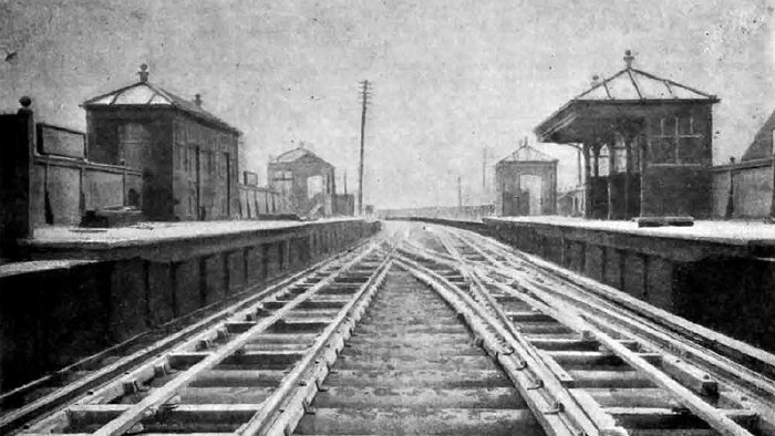
The railway in 1893. From The Engineer.
|
The Liverpool
Overhead Railway. Part of an article from The
Engineer.
The railway is designed for the
use of any of the well-known systems of mechanical
haulage, but the electrical was ultimately selected,
and that which relates to the working of the line by
electricity has been designed and carried out by Mr.
T. Parker, M.I.E.E., as engineer and manager for the
Electric Construction Corporation. On the line,
which, as we have already said, is six miles in
length, double track, there are fourteen stations,
with crossover roads at each intermediate station,
and double crossovers at the terminal stations. It
is eventually intended to run a three minutes'
service, and generating plant bas been provided for
this. There are some moderately sharp curves on the
line; the maximum being six chains radius. The
maximum distance between any two stations is 1200
yards, and the minimum distance 300 yards. The
journey from one end of the line to the other will
be completed in about thirty minutes, including half
a minute stop at all stations. In the first instance
rolling stock is only being provided for a five
minutes' service. It is hoped that the traffic will
be carried with the expenditure of about 7 lb. of
coal per train mile.
The generating station and
plant occupies a position close to the structure and
approximately in the centre of its length. The
arches under the existing coal railway have been
utilised for the generating station. It is intended
that the line shall eventually be extended at each
end by a length of 1½ miles, this bringing up the
total when completed to nine miles.
The boilers are six in number
and of the Lancashire type, 30 ft. by 8 ft.,
constructed for a working pressure of 120 lbs. per
square inch, fired by Vicars' mechanical stokers,
the coal supply being drawn from hoppers overhead,
into which the trucks on the existing coal railway
are emptied. Coal supplied to the various boilers by
means of a conveyor, and the feed passes through a
Green's fuel economiser, consisting of 384 pipes.
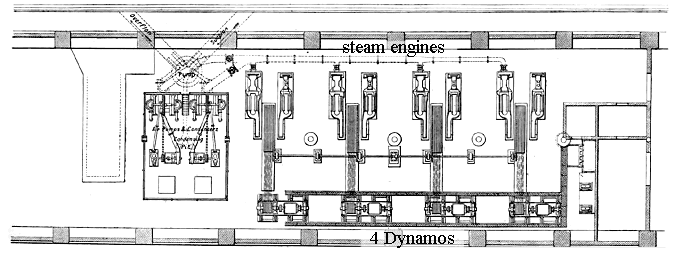
The generating station.
The boilers and steam pipes are
covered with Leroy's none conducting composition.
The dynamos are driven by four horizontal coupled
compound engines, with Corliss valve gear and each
capable of indicating 400 horsepower, with 120 lb.
steam pressure, at 100 revolutions per minute. The
cylinders, 15½ in. and 31 in. diameter, 36 in.
stroke. Valves fitted to all cylinders. The
flywheels are 14 ft. diameter, grooved for nineteen
l¼ in. diameter ropes. Independent surface
condensing plant is used, divided into two units,
each capable of condensing steam from three of the
main. engines, running under full load. The
condensing water is taken from the dock adjoining
the generating station, and passed through brass
tubes. The air and circulating centrifugal pumps are
driven by small compound vertical engines, having
Ferguson’s patent triangular connecting rods. The
cylinders, 7½ in. and 15 in. diameter,12 in. stroke.
As auxiliary machinery there are two pumping engines
for boiler feed, each capable of supplying four
boilers. One engine for driving stoker and conveyor,
10 indicated horsepower, and two small engines for
working the scrapers on the economiser. All steam
and feed pipes are arranged to give a duplicate
service between boilers, engines, and pumps.
Arrangements are also made so that the engines may
exhaust into the atmosphere in case of water not
being obtainable at any time for condensing.
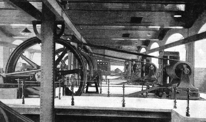
The four Elwell-Parker type dynamos.
Four Elwell-Parker shunt-wound
dynamos, each giving an output of 400 volts and 475
amperes, at 400 revolutions per minute, are used.
The magnets are of the double horseshoe type, fixed
vertically, divided on the horizontal centre line,
so that the top half can be readily lifted off to
allow of examination or removal of the armatures.
The pulley is carried between two bearings, and a
coupling being inserted between the pulley and
armature shafts, allows the latter being taken out
without taking off ropes, dismounting pulley, or
interfering with the set of the bearings. Each
dynamo is coupled up through an ammeter to a double
pole automatic magnetic cut-out, which also answers
the purpose of main switch. All the machines couple
in parallel on to omnibus bars, from which the
current is taken by underground "armoured" cables to
the conductors on the line, a larger automatic
magnetic cut-out being inserted, carrying the whole
of the current. Multiple contact switches and
resistance coils in the shunt circuit arc employed
for regulating the electromotive force of the
machines.
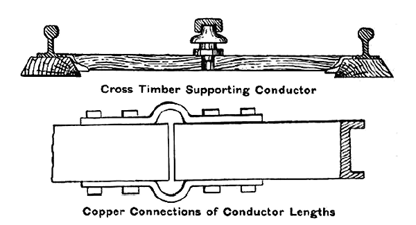
The conductor, consisting of a
steel channel, is carried the whole length of both
the up and down lines between the ordinary rails,
the latter forming the return circuit. The steel
channel is carried upon pot insulators, supported by
cross timbers between the longitudinal sleepers. The
surface of the steel channel, forming the centre
conductor, is ⅞ in. higher than the top of the
ordinary rails. At the crossover roads the conductor
is bent so as to run parallel for a short distance
on each side of the ordinary rails, but leaving
ample clearance to prevent arcing across. The
current is collected from the surface of the steel
channel by means of cast iron shoes loosely hinged
to insulated iron strips carried by the bogies. The
shoes are made much wider than the conductor, so as
to stretch across at the crossover roads from the
conductor on the one side to the conductor on the
other side of the ordinary rails. A collector is
fitted to each motor bogie.
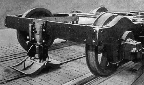
The conductor and the collector.
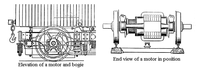
The carriages, two of which
form a train, are in length over end pillars 45 ft.;
the width over side pillars, 8 ft. 6 in. The
carriages are mounted on two four-wheeled bogies,
one of which carries a motor as shown. The centres
of the bogies are 32 ft. apart. The wheelbase of the
bogies is 7 ft., and the wheels are 2 ft. 9 in.
diameter. They carry 57 passengers; 16 first class
and 41 second class.
As each carriage is fitted at
one end with a driver box and necessary switch and
brake gear for controlling the work, there is no
shunting at the terminal stations, the driver
changing ends. The gangway between the two cars
gives a clear passage through for the guard.
The motors on each train are on
the leading and trailing bogies. Six incandescent
lamps light each carriage, supplied with current
from the centre conductor, the same as the motors.
The carriages are fitted with
Westinghouse brakes, with compressed air stored in
receivers carried under the carriages, and these
being charged by an air compressing plant fixed at
the generating station at the north end of the line.
Hand screw brakes are also provided.
The armatures of the motors are
mounted direct upon the axles. Ten revolutions of
the axle per minute gives a speed to the car of one
mile per hour. The maximum speed necessary to do the
journey in the time specified is approximately 26
miles per hour, or 260 revolutions of the motor per
minute. The motors are series wound. |
|
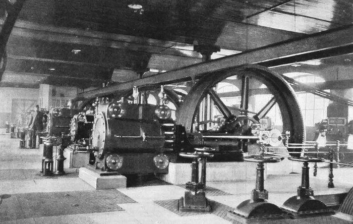
The steam engines in the generating station.
From The Engineer.
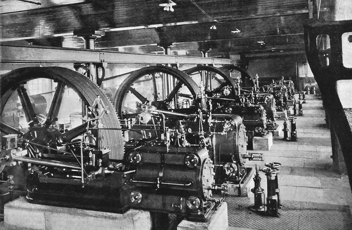
Another view of the steam engines in the
generating station. From The Engineer.
Thomas Parker presented a paper on the Liverpool
Overhead Railway to the Institute of Civil Engineers on Tuesday 2nd
March, 1894. The paper was called “The Electrical Equipment of the
Liverpool Overhead Railway”:
|
The
Electrical Equipment of the Liverpool Overhead Railway
by Mr. T. Parker, M.. Inst., C.E.
The plant was required to run a three-minute service on six
miles of double track. In designing it, curves were drawn of the
energy required at any point along the line of one loaded train
with various accelerations. etc., to meet the timetable service.
From these curves the power required at the generating station
was calculated, and four dynamos were arranged, yielding 475
amperes at 500 volts and 420 revolutions, or 1,200 E.H.P. in
all. The dynamos were of the double-line type, rope driven, with
pulley between two bearings, so that the armature could be taken
out without disturbing the ropes.
The electrical efficiency of the dynamos was 97.77. The
switchboard, specially designed for safety and simplicity in
working, was fully described. The main current passed to the
line through a main magnetic cut-out, to break circuit at 3,606
to 4,000 amperes. The conductor was of steel, 4 square inches in
section, supported on porcelain insulators. There were no
feeders, and the return circuit was through the rails, which
were bonded. At each station there was a crossover road. The
conductor was broken at these points, and the collector bridged
across over the main rails without breaking circuit.
It was necessary that the cars should be of the double-bogie
type; it was, therefore, difficult to design motors to give the
power necessary on standard bogie frames. Finally a type was
adopted, as patented by Mr. Eickemeyer, which gave complete
satisfaction. The motor occupied the front half of the
bogie-truck. The weight of the magnets was taken off of the
axles by adjustable springs, and the magnets were kept in
horizontal position by a lever arm fixed to the bogie-frame.
Each car was complete with motor and switchgear to run
independently. Two cars were coupled together to form a train.
Either the driving or trailing motor could be plugged out of
circuit at will. A Westinghouse air-brake was attached to the
car, also the usual hand-brake. The stations were lighted by
50-volt glow-lamps, run off accumulators fixed at the station
and charged from the main dynamos.
The efficiency of I.H.P. to E.H.P. on the line was taken with
carefully calibrated instruments in the presence of the
Engineers. The tests extended over 3½ hours. The mean value of
seven tests of No. 1 Engine gave 88 per cent. I.H.P. to E.H.P.
Curves were given of the power consumed during an experimental
run of one train completing 51 miles in 24 minutes, 57 seconds,
and 23 minutes, 47 seconds, with stops of 25 seconds at each
station. The power required was 44.4 I.H.P. and 46 E.H.P.
respectively. To compare this with actual running, curves were
given from daily log-sheets showing the effects on the
generating station of the alteration to the train service. The
advantage of a large number of trains in pulling down the
maximum current per train was apparent. With seven trains this
was twice, and with twelve trains only 1½ times the average
current per train. With twelve trains running, the average
demand for power continuously was 37 E.H.P. per train.
A comparison of coal used when the train service varied was
given. During April and part of May seven trains were running at
one time, and the coal used was 22.5 lbs. per train mile. From
June to October there had been a 5 minute service from 9 a.m. to
5-30 p.m. The coal used per train mile for the four months of
June, July, August and September, was 17.8 lbs., or making
allowance for charging batteries, say I7 lbs. per train mile.
The price of the Lancashire slack, which was used till the
latter part of August, was 5s. 10d. per ton, but since that
date, owing to the strike, the price for coal from various
sources had varied up to 17s. 6d. per ton. Under the agreement
the contractors had to run the service of trains for 3½d. per
train mile, on a full service of 2,400 miles per day, but as
only five and one eighths miles of line were open, they received
4d. per train mile, and for current to charge lighting
batteries, 7d. per Board of Trade Unit. Figures were given of
the actual working costs for July, August and September, 1893,
which were 3.44, 3.70, and 4.07 pence per mile respectively. The
increased cost of running for August and September was fully
accounted for in the item of coal, and as the railway company
had not employed as frequent a service as at first anticipated
(this being only 1,350 miles per day) the figures showed most
favourably, it being evident that, with coal at an average
value, the line could be run at a cost well within that
guaranteed by the contractors.
|
|
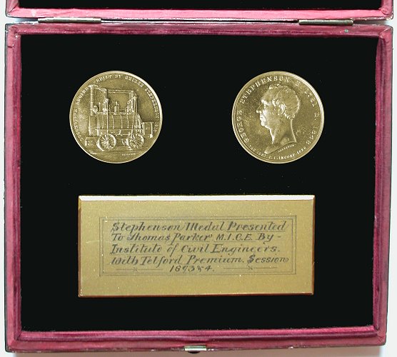
The paper was a great success, and Thomas was
awarded a George Stephenson Medal and a Telford Premium for his
efforts. This can be seen in the following transcript of the letter
that he received from the institution:
|
Sir, I am instructed to inform you that the
Council of the Institution of Civil Engineers has awarded you a
George Stephenson Medal and a Telford Premium for your paper
entitled “The Electrical Equipment of the Liverpool Overhead
Railway”. The formal presentation will take place at the first
ordinary meeting of next session on the second Tuesday in November,
when it is hoped that you will be present to receive the premium
awarded to you.
I am, Sir, your obedient servant, James Forrest,
secretary.
To Thomas Parker, Esq., M. Inst. C.E.
Manor House
Tettenhall
Wolverhampton
|
|
Thomas received a letter of congratulation on the
award, from his friend Thomas Bantock, J.P.
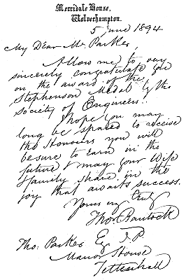 |
Merridale House,
Wolverhampton
5th June, 1894
My Dear Mr. Parker,
Allow me to congratulate you on the award
of the Stephenson Medal by the Society of Engineers.
I hope you may long be spared to receive
the Honours you will be sure to earn in the future and may
your wife and family share in the joy that awaits success.
Yours Truly
Thomas Bantock, J.P.
Tho. Parker Esq., J.P.
Manor House
Tettenhall |
|
Thomas's Stephenson Medal.
Courtesy of
the library and archives of the Ironbridge Gorge Museum, at
Coalbrookdale. |
 |
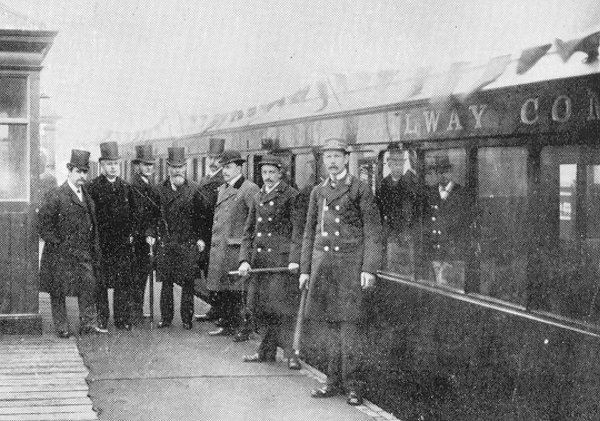
The opening ceremony of
the Liverpool Overhead Railway.
The group L. to R. is as follows:
Thomas Parker; Sir Douglas Fox, joint
engineer; Francis Fox, younger brother and partner of
Douglas; James Henry Greathead, civil engineer. |
|
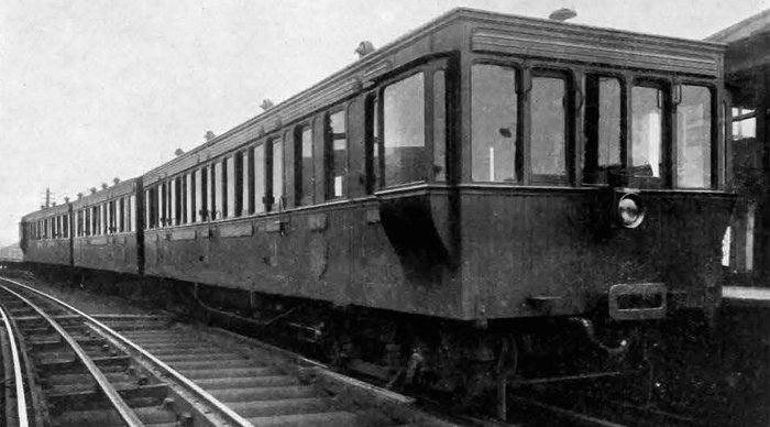
One of the locomotives in operation.
From 'The Engineer' 24th November, 1911. |
|
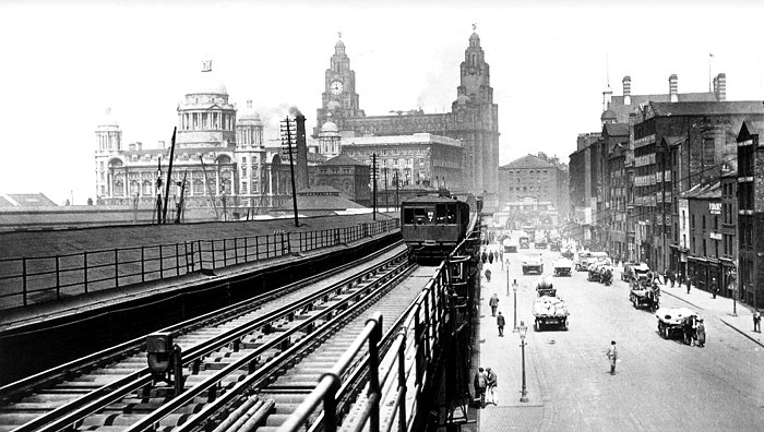
A train passes between Canning
Dock and Strand Street. From an old postcard. |
|
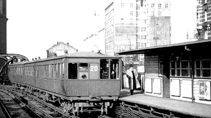
A train pulls into James Street
Station. |

|
Return to the
previous page |
|