 |
The Electric Construction Corporation developed the
overhead-wire tram system that began operating in 1893 when the South Staffordshire Tramways
were electrified. |
|
South Staffordshire Tramways.
From The Engineer, 18th November, 1892.
Early in the present year
the South Staffordshire Tramway Company entered
into a contract with the Electric Construction
Corporation, of Wolverhampton, for the equipment
of a section of its lines with plant for
electric traction on what is generally known as
the trolley wire system, the lines having
hitherto been worked by steam locomotives. The
plant is now practically completed, and the
inspection by General Hutchinson and Major
Cardew, on behalf of the Board of Trade, took
place on Saturday, November 12th, so that the
electric cars will very shortly come into
service.
The lines over which the electric cars are to
be run extend from the junction of Holyhead Road
and Bridge Street in Wednesbury, through the
centre of the borough of Walsall, to Bloxwich,
with two branch lines, one running from the
Pleck to Darlaston, and the other from Walsall
to Mellish Road. The length of streets occupied
by the tramways is just over eight miles, six
miles having a single line with turn-outs, the
other two miles having a double line, making a
total length of track, and therefore of trolley
wire, of over ten miles. The route taken by the
lines is shown on the map - Fig. 5 - which also
indicates the position of the generating station
on the line between the Pleck and Darlaston.
Fig. 5. A map of the tramway. |
|
The generating station at Pleck, Walsall. |
|
The generating station is
on the side of the canal, and has a basin for
receiving the barges bringing coal, which
discharge directly into the boiler room. The
canal water is used for condensing.
The general arrangement of
the buildings and plant is shown on the plan and
section - Figs. 6 and 7. The three boilers are
of the Lancashire type, 7ft. diameter, 30ft. in
length, designed for a working pressure of 120
lb. per square inch. The three engines, which,
together with the boilers, were made by Messrs.
J. Musgrave and Sons, of Bolton, are of the
horizontal coupled-compound pattern, each easily
capable of indicating 125 horse power with the
above steam pressure, when running at a speed of
100 revolutions per minute. The cylinders are
10½in. and 20in. diameter, 30in. stroke, both
cylinders being fitted with Corliss valve gear;
the flywheels are 10ft. in diameter, and grooved
for seven l¼in. diameter ropes. A surface
condenser is attached to each engine. The steam
and feed pipes are arranged so as to give a
duplicate service between the engines, boilers,
and pumps. |
|
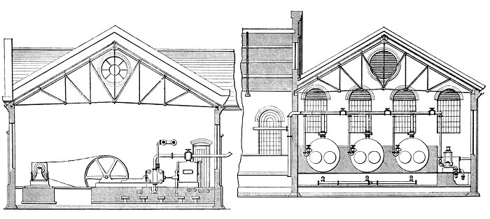
Fig. 6. The generating station. |
|
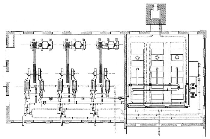
Fig. 7. A plan of the generating station. |
| Arrangements are also provided so that the
engines can be run non-condensing if required.
The dynamos, one of which is driven from each
engine by means of cotton ropes, are of the
usual Elwell-Parker type, and give an output of
260 amperes at 300 volts, when running 400
revolutions per minute, the field magnets being
shunt wound. The driving pulleys are carried
between two bearings, and there is a coupling
between the pulley and armature shafts, so that
the latter can at any time be removed without
taking off the ropes or dismounting the pulley. |
| Each dynamo is connected by cables carried
under the floor to a patent Elwell-Parker
automatic magnetic contact, which also acts as
the main switch for the machine. These
contacts are adjusted so that, in the event of
an excessive current being demanded from the
machines - due to any accident or short circuit
on the lines - the circuit is opened, and any
damage to the machines prevented.
All three machines feed in parallel on to
common omnibus bars, between which and the
feeders taking current out to the line there is
a simple main switch. Ammeters are provided in
each dynamo circuit, and a voltmeter with large
dial indicates the electromotive force across
the omnibus bars.
Multiple contact switches and resistance
coils are connected in the shunt circuits for
regulating the electromotive force.
A section of the switchboard showing the
arrangement for each machine is illustrated in
Fig. 4. |
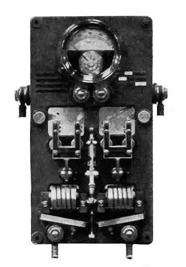
Fig. 4. The switchboard. |
|
From the generating station
the current is supplied to the 0 gauge copper
trolley wire by underground feeders, these being
insulated with vulcanised bitumen, lead
sheathed, and armoured with a double layer of
steel tape, so that they can be laid directly in
the ground without further protection; the
lengths and sections of the feeders are
indicated in the map - Fig. 5.
The return circuit is
completed through the rails and earth. At
distances of approximately half a mile apart
connections are made between the feeders and
trolley wire by means of cables drawn up inside
the posts. Each section of trolley wire is fed
into at both ends, the current passing through
fuses placed in an underground box - Fig. 8 - at
the foot of the feeding posts. These fuse boxes
are made on the diving bell principle, to
prevent any possibility of water accumulating in
them and rising sufficiently high to reach the
connection. The covers are easily drawn up to
allow of examination or insertion of new fuses.
The map - Fig. 5 - shows the position of the
feeding points and fuses. |
|
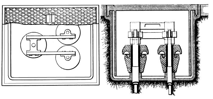
Fig. 8. Underground fuse boxes. |
|
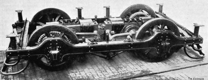
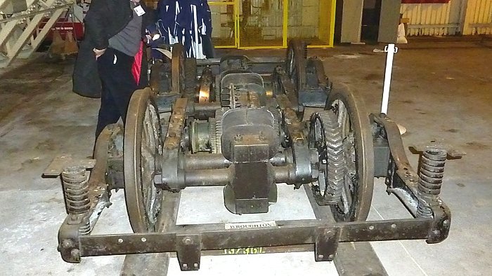
Fig. 2. An under truck with motors. |
| The trolley wire is carried at a height of
20ft. from the surface of the streets by poles
along one side of the road only; arms projecting
from the poles - Fig. 7 - carry the insulators
supporting the wire. A special arrangement,
suggested by Mr. Dickinson, the Tramway
Company's engineer, makes it unnecessary that
the trolley wire should be at a regular distance
from the centre of the rails, the collector
being designed so as to allow a variation of
several feet. Where there is a double line of
rails the pole arm carries two insulators and
two trolley wires, one for the up and one for
the down line. Automatic overhead switches are
fixed at the turn-outs, so as to guide the
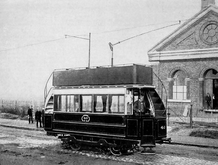
collector wheel along the right wire. Fourteen
cars made by Messrs. Brown, Marshall, and Co.,
and the Lancaster Wagon Company, are being
supplied for the equipment of the line, each
carrying forty passengers, eighteen inside and
twenty-two outside. The collector is fixed on
one side of the roof of the car, the arrangement
being clearly shown in Fig. 7. |
|
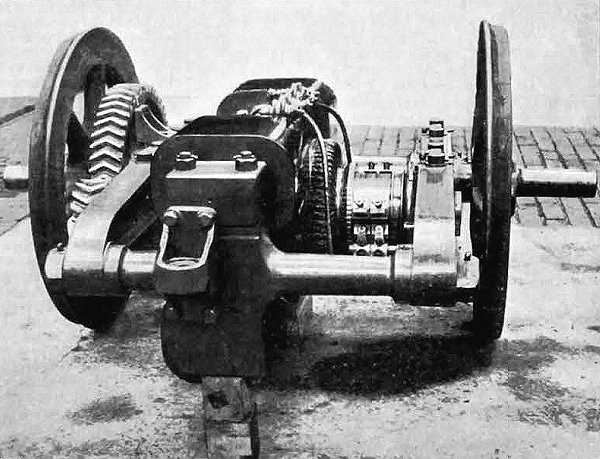
Fig. 3. An Elwell-Parker motor. |
| The under trucks - Fig. 2 - carry two Elwell-Parker
series wound motors - Fig. 3 - each capable of
running continuously with a load of 15
horsepower, the normal speed being 400
revolutions per minute; the armatures are geared
up to the axles by means of cast steel double
helical wheels and pinions, having a ratio of 4
to 1. One motor is considered to be amply
sufficient to take a fully loaded car up the
heaviest gradient of 1 in 28 occurring on the
line. The practice of using two motors on each
car appears to have been brought over from
America, where the lines are not so well laid,
and where, also, they have to contend with snow
and ice throughout the winter. On very few lines
in England do we consider that it will be
necessary to use two motors, although it will be
necessary that the one motor shall be more than
15 horsepower, unless a simple form of gear for
varying the speed with a constant speed of motor
be used. Driving switches are fitted at both
ends of the car, and arranged so that either or
both of the motors can be in use, the regulation
of speed being effected by putting resistance
into the motor circuit. The
whole of the electrical plant has been designed,
manufactured, and installed by the Electric
Construction Corporation, who are also
responsible for the other portion of the plant
supplied to them by various firms as
sub-contractors. The running of the line is also
in the hands of the Electric Construction
Corporation, they having undertaken to work it
at a fixed charge per car mile for a number of
years. Mr. Alfred Dickinson has been appointed
to superintend the working on their behalf. |
|
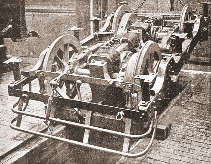
Another photo of an Elwell-Parker under
truck.
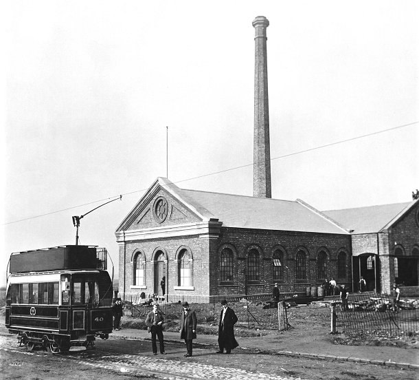
The South Staffordshire Tramways
generating station.
The following description of the tramway is from the Railway
Engineer, volume 14, number 1, January, 1893:
|
The South Staffordshire Tramways have an aggregate
length of about 23 miles. They connect Darlaston,
Wednesbury, West Bromwich, Handsworth, Great Bridge,
Dudley Port, Dudley, Walsall, and Bloxwich with each
other, and last year 4,000,000 passengers were
carried.
About nine miles-viz., from Darlaston and Wednesbury to
the Pleck, thence to Walsall Bridge, where the line
again separates, one branch going to Bloxwich and the
other to Lichfield Road - has been fitted to work by
electricity upon the over-trolley wire system.
The installation has been carried out entirely by the
Electric Construction Corporation of Wolverhampton. The
sub-contractors for the cars were the Lancaster Carriage
and Wagon Co., and Brown, Marshalls & Co., for the
stationary engines and boilers of 150h.p. Messrs.
Musgrave & Son, of Bolton, and the posts to carry the
overhead wire were divided between Messrs. James Russell
& Sons and Messrs. John Russell & Co.
The motors are of the Elwell-Parker type. The posts are
placed at the side of the road, and the bracket arms
carrying the trolley wire stretch out over the road 7 to
10ft., but give a clear height of 21 ft. By a kind of
universal joint the collector is allowed a variation of
several feet, so that it is not necessary for the
trolley wire to be directly over the middle of the line.
|
|
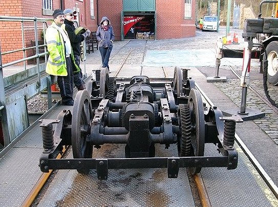
One of the tram trucks from the South Staffordshire Tramways
has survived. It was acquired by the London Science Museum in
1912, and went directly from the Darlaston tram depot to be put
into store. It has recently moved to the National Tramway Museum
at Crich, and must be the oldest tram truck in the world that is
still in its original condition.
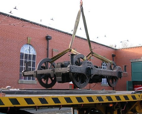 |
The truck arrives at Crich.
Courtesy of the National Tramway
Museum. |
| The truck, after being
unloaded from the transporter.
Courtesy of the National Tramway
Museum. |
 |
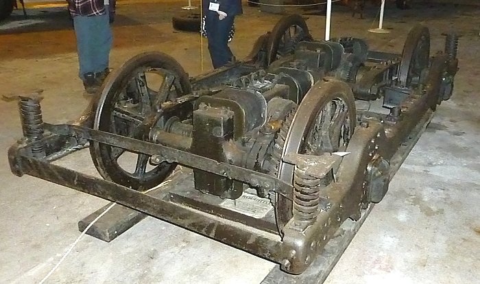
The truck at the Science Museum's store.
Courtesy of
Another view of the truck at the Science
Museum's store. Courtesy of
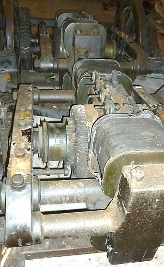 |
This close-up view of the
truck clearly shows the two electric motors. The gears
can also be seen on the back wheels. The commutators
appear to be in good condition, but unfortunately the
brush gear is missing.
Courtesy of
|
 |
Return
to the
previous page |
|