 In the course of our notice of the
recent Show of the Royal Agricultural Society at Birmingham, we had
occasion to mention a new steam pump, constructed on Messrs. Parker
and Weston's patent, which was exhibited there. Of this pump, which
is manufactured by the Coalbrookdale Company, Shropshire, we now
give engravings, our illustrations showing two different
arrangements. The distinguishing feature of this pumping engine, as
in all others of the direct acting class, consists mainly in the
valve movement in the steam cylinder. In designing this valve motion the patentees had two
objects in view, firstly, to get a positive motion by means of a
simple valve moved by the steam alone without the use of tappets and
other extraneous gear, and, secondly, to use the steam expansively
in the cylinder. How this is accomplished will be readily understood
from the accompanying illustrations.
Two forms of main steam valve are
used, one being an adaptation of the old Cornish valve, as shown in
Figs. 1 to 7, and the second being a common slide valve moved by two
pistons in exactly the same way as the preceding, and shown on Figs.
9 to 13. It was a pump fitted with the
latter arrangement which was shown at Birmingham.
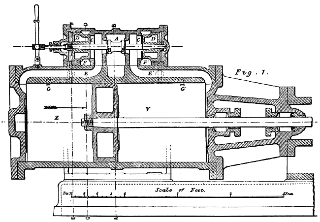
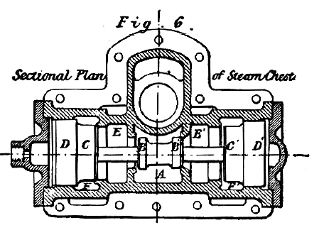
In our engravings, Fig. 1 is a
longitudinal section of the steam cylinder and valve chest. A is the
steam space in the centre of the chest, B B are the steam valves;
these are in one piece, and fixed to the steel spindle b; C C'
are the exhaust valves; D D' are the valve pistons, which are cast in
one piece with the exhaust valves. The valve chest is semicircular
in form, and has four diaphragms cast across it; these have circular
seats formed upon them, against which the valves work, the steam
valves opening towards the centre, and the exhaust valves opening
outwards. The valves are made of cast iron, and owing to the short
travel and the ease with which they come against their seats, they
are found to work a long time without any appreciable wear.
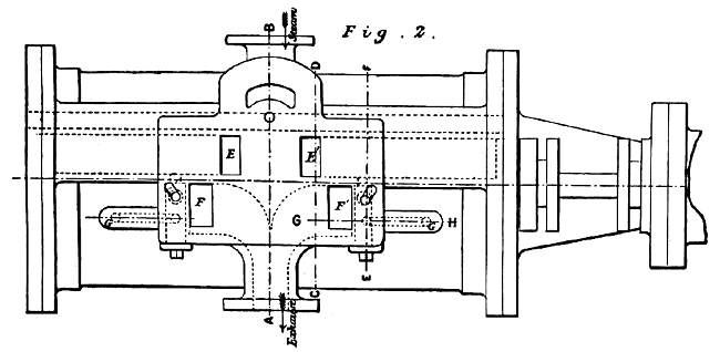
Fig. 2 is a plan of the cylinder
with steam chest removed. The steam and exhaust branches are cast on
the cylinder, and the steam chest can, therefore, be removed without disturbing the pipes. E E'
are the main ports to the cylinder, and F F' the exhaust passages; G G'
are passages leading from the cylinder to the spaces behind the
valve pistons D D'; in these passages are inserted the ball valves H H'.
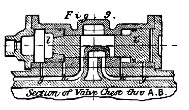
These work in brass cages, and are accessible from the outside by
unscrewing the brass plugs shown on Fig. 3. The use of these ball
valves will be seen as we proceed.
| The motion of the valve is as follows: Suppose
the space A to be filled with steam and the main
piston to be travelling in the direction indicated
by the arrow, as shown on Fig. 1, steam would then
pass through the valve D and fill the Z end of the
cylinder. The series of valves would remain as
shown until the main piston passed over the
reversing port G'; when the live steam rushes up the
opening and blows the ball H' against the passage
into the main steam port and fills the space behind
the valve piston D'.
As the opposite end D is at the same time exposed
to the pressure of the live steam from being in
communication with the Z end of cylinder the two
valve pistons DD' are thus placed in equilibrium.
|
 |
The surface of the exhaust valve C' has only the
exhaust pressure upon it, whilst C has the full pressure of the
steam; this preponderance of pressure on C causes the whole series
of valves to be instantly shot over and the Z end of cylinder put in
communication with the exhaust. The steam then fills the opposite
end of the cylinder and the main piston moves in the opposite
direction, when the piston uncovers the hole G, and the same motion
of the valves takes place at the other end.
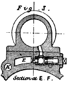
The ball valves play an important
part in insuring the certainty of action of the main steam valve. It
has already been stated that when the piston passes the reversing
hole G', the entering steam blows over the ball, closes the opening
to steam port at P (see fig. 3), and allows the steam to get behind
the valve piston D'. The instant the valve is reversed the port E is
filled with steam, and the end of the cylinder Z placed in
communication with the exhaust; but by this time the piston has not
moved sufficiently far on the return stroke to cover the reversing
port G'; this is now also open to the exhaust, which would have the
effect of releasing the pressure from behind the piston D', and thus
destroy the stability of the valve movement.
But the steam from the
port E at this instant blows the ball over and closes the connection
with the cylinder through the passage G', and allows the full
pressure of steam from the port E to be kept on the piston D', thus
holding all the valves on their seats during the stroke of the
engine. The motion of the valves is absolutely certain, even at a
crawling speed, and must give a full opening for steam and exhaust
at every stroke, thus differing from those steam-moved valves, whose
steam admission depends upon the use of tappets, the main valves of
which cannot be insured to move the full travel when the engine is
working at a slow speed.
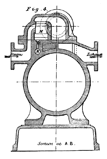 |
The expansion of the steam in the
cylinder is effected by means of a valve entirely distinct in its
action from those which control the main piston. The steam is
admitted through a branch on the side of the cylinder, and then
passes by an oblong shaped port to the centre of the steam chest
through the expansion valve. The time of the admission of steam to
the upper part of the chest is regulated by a circular valve M (see
Fig. 4), which can be raised at any desired point of the stroke by
the admission of the steam under its lower surface. This under
surface being of greater area than the top, the pressure of steam
upon it overcomes the resistance of the incoming steam by raising
the valve, cuts that steam off from the steam chest.
The
construction and action of this valve will be readily understood by
reference to the Figs. 4 and 8. K is a hole running parallel with
the cylinder, and bored throughout its entire length, and in this
hole is fitted a brass tube s; this tube is turned round by
means of the spindle and hand wheel, and is kept
steam tight by the stuffing box at the end. |
| Holes are drilled at intervals along the
cylinder corresponding to the various points of cut off. The tube is
also perforated, but not in the same horizontal line as the steam
cylinder. By turning the tube round, one of the holes at each end is
brought opposite a corresponding hole in the cylinder. When the
piston passes those holes the steam rushes along the tube, opens the
valve L, and raises the expansion valve M, abutting off the further
supply of steam to the chest, and allowing the steam already in the
cylinder to expand to the end of the stroke. The use of the valve r in
the tube is to prevent the cut off taking place before half stroke.
The valve between its faces is longer than the distance between the
seats; one or both ends of this valve can thus be open at one time.
It is obvious, therefore, that as the piston travels over the holes
o, p, q, the steam would find its way along the tube and
raise the expansion valve, but the steam shuts the valve r
until the piston has uncovered the required hole on
the other side of the centre, when the valve being
thus put into equilibrium the steam finds its way
below the expansion valve and produces the desired
result.
By an exceedingly simple arrangement the expansion
valve is made to serve the purpose of a cataract governor, and
causes the engine to pause at each end of the stroke. |
 |
 |
This is
effected by placing a small valve (marked L in Fig. 4, and l
in Fig. 8) in the passage leading to the expansion valve; this valve
opens upwards for the admission of steam, the exhaust from the
underside of the expansion valve takes place through a small
orifice, the area of which is regulated by a screw (not shown on the
engraving); by this means the engine can be made to pause at the end
of the stroke, as no new steam can be admitted to the chest until
the expansion valve is allowed to open. |
| Figs. 1 to 8, above referred to, show the valve
gear as applied to a direct acting pumping engine
with an 18 in. steam cylinder, and 8 in. pump with
36 in. stroke, now at work in a colliery in South
Wales and forcing 1300 gallons per hour to a height
of 252 ft. |
 |

 |
The makers are also preparing a compound pumping
engine on the same principle, steam being carried to
half stroke in the high pressure cylinder, then
passed into a low pressure cylinder of three times
its capacity and afterwards discharged into a
condenser. From diagrams which have been taken
from some of these engines the saving in steam is seen to be very
marked, and this fact removes the objection commonly urged against
this class of pumping engine on the score of comparatively great
expenditure of steam. |
 |
As we have remarked on former
occasions, the economy of steam in compound direct-acting engines
cannot be excelled by the best form of Cornish pumping engines,
while with the former type the first cost is a mere fraction of that
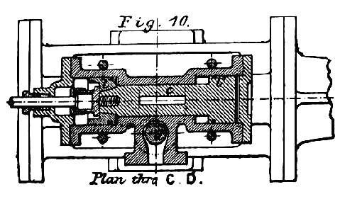
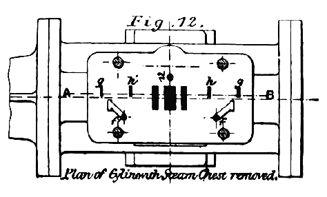
incurred with the latter. Figs. 9 to 13 show another form of steam
moved valve, consisting of a semicircular slide
valve moved by two pistons. Fig. 9 is a section
through steam chest. |
| The slide
valve is made in a separate piece from that forming the piston l'
and the centre c, and has merely end contact with them; the
pressure of steam acting on the back of the valve keeps it tight to
the face as in a common slide valve. The steam is admitted to the
chest through an expansion valve d. |
 |
| The cut off is not made
variable in the smaller sizes of pumping engines, the steam being
generally cut off at two thirds of the stroke; one hole, n,
is drilled into the cylinder immediately under the expansion valve,
the valve is thus raised each time the piston passes the hole. When
it is desired to give the valve steam during the whole of the stroke
the stop e is screwed down and thus prevents the valve from
rising. The movement of the valves will be readily understood from
the following description and an examination of the engravings. |
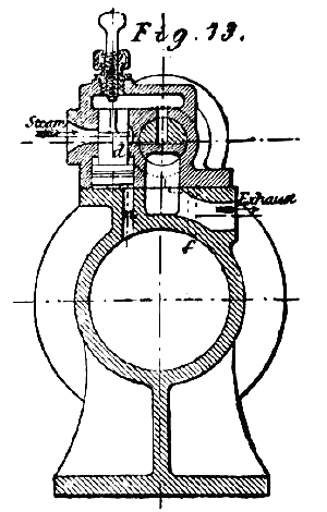 |
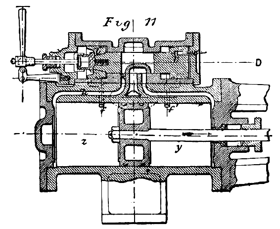
In Figs. 11, 12, and 13, f f'
are passages communicating with the main steam cylinder and the
small cylinder in which the valve pistons l l' work. In these
pistons small ports are formed having certain relative positions to
the aforesaid passages f f'. Other passages g g', lead
directly from the main steam ports to the outer end of the valve
cylinder, and h h' are
passages from the steam ports to the inner end of the valve
cylinders. Suppose the piston to be travelling in the direction of
the arrow, the slide valve would be in the position shown in Figs.
9, 10, and 11, and steam would be passing through the steam port
k, and filling the end of the cylinder z.
Under these
conditions live steam is also filling the passages g and h,
and acting on both sides of the piston l, at the same time
the exhaust is passing out from the end of cylinder y through
the main port under the slide valve, and thence to the atmosphere or
condenser; both sides of the piston l' are also open to
the exhaust.
|
The valve is retained in this position until the completion
of the stroke of the engine by the pressure on the outer or larger
side of the piston l'. When the main piston uncovers the hole
f' the steam rushes through and fills the space behind the
valve piston l', and thus the outer sides of both the valve
pistons are subjected to equal steam pressures, but the inner
surface of l has the live steam on it whilst the inner
surface of l' has only the exhaust pressure, the extra
pressure on l therefore shoots the valve over to the opposite
end.
As the main piston in reversing
has to pass back over the passage f' there might be a slight
tendency of the valve to falter, or not to travel the whole
distance, owing to the slight loss of pressure which would occur
behind the piston l' when the main piston was passing the
hole. This is prevented by the following means: Let the slide valve
open by only the smallest amount, the main steam port will be filled
with steam at the same time the outer end or the valve piston l'
will have uncovered the passage g', and admitted a second
supply of steam behind the piston 1'.
By this time also both
sides of 1 will be open to the exhaust which has taken place
in the z end of cylinder, and the valve is thus carried the
full stroke by the pressure acting on the outer end of piston l'.
It will thus be seen that there are two distinct causes at work to
move this slide valve, following each other with a rapidity and
certainty that has never been excelled in any single steam-moved
valve. The motion can be perfectly cushioned by the small quantity
of steam squeezed up on the inner side of the piston l' when
it crosses
the opening h'. Altogether
the arrangements of valve gear we have described have been very
ingeniously and carefully worked out, and we expect hereafter to
have more to say concerning the pumping engine to which these
arrangements have been fitted.
|