| An article from The Engineer, 9th
November, 1934:
Villiers Engineering Works
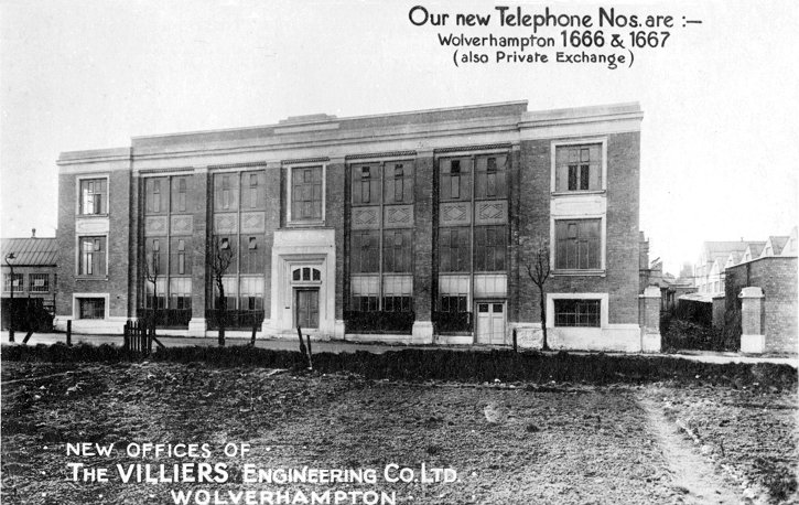
In a recent visit which we paid to the Marston Road
Works of the Villiers Engineering Company, Ltd., at Wolverhampton, our
attention was drawn to the fact that in addition to producing a weekly
output of tens of thousands of free wheels and sprockets, the firm has a
manufacturing capacity of no less than 1,100 small two-stroke engines per
week. The works have been newly built and planned, and are complete with the
latest specialised machinery for their work, and some account, therefore, of
their history, their technical equipment, and the engines manufactured will,
we feel, be of interest to many of our readers.
Plan of the Marston Road Works.
Beginnings and Development
The Villiers Engineering Company, Ltd., was formed in
1898, and its original works were on small premises in Upper Villiers
Street, Wolverhampton. Its first products, were pedals for bicycles, but the
making of these was later discontinued, and in 1904 the manufacture of Villiers free wheels was
begun. That side of the firm's activities has continued to increase
steadily, and today the company is, we are given to understand, one of the
largest manufacturers of free wheels in the world.
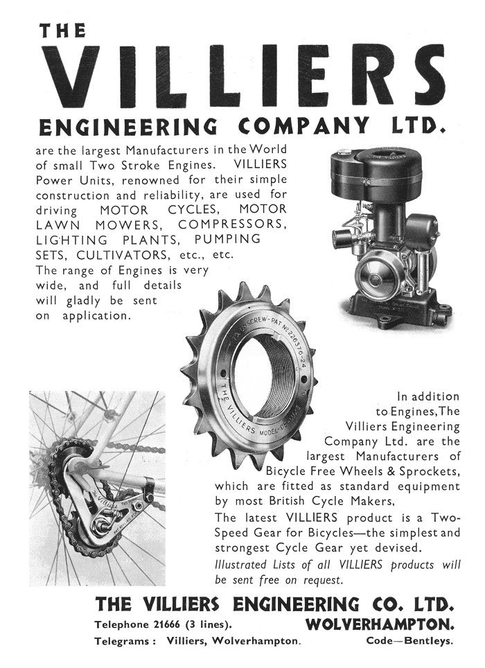
That the firm has not
stood still in this side of its work is shown by the fact that there is
being exhibited at the nineteenth International Bicycle and Motor Cycle Show
at Olympia this week a new type of Villiers two-speed gear. It consists of
two sprockets mounted on the rear hub of a cycle, and connected by a free
wheel, so that one sprocket can overrun the other. The drive from the main
sprocket is transmitted through two further sprockets mounted on a
countershaft, and by means of three driving pins the hub sprockets can be
run independently or connected, this action representing a change of gear,
giving an increase of speed of about 25 per cent.
It is, however, rather with the engine side of the
firm's work that we propose to deal. The first Villiers internal combustion
engine using petrol was produced in 1912, and was a small single-cylinder,
four-stroke unit with an overhead inlet valve which worked in conjunction
with a two-speed gearbox. That design was, at that date, the directors felt,
somewhat ahead of its time, and it was immediately decided to produce a very
simple two-stroke engine, which was built shortly afterwards in the same
year. Since that time the firm has concentrated on the production of
two-stroke engines alone, and from small beginnings, when a good deal of
prejudice had to be overcome, the demand for such engines has steadily
increased, and now requires a works capacity of 1,100 engines per week.
We shall describe later some of the principal engine
types, and enumerate some of the varied uses to which they are put. Before
doing so, however, reference may be appropriately made to the firm's
patented flywheel magneto, which forms an integral part of Villiers engines,
and is fitted to many engines, both industrial and marine, of other makes.
The early Villiers engines were all equipped with horseshoe pattern flywheel
magnetos, which at that time were principally produced in Germany. During
the war period, however, the firm started to manufacture its own magnetos,
and after careful consideration it was decided to adopt a flywheel type,
which, as the engine was already fitted with a flywheel which would house
it, saved a projecting bracket, a chain, and two driving sprockets. After
extensive experiments, the Villiers flywheel-type magneto was adopted in
1919 as standard equipment on all engines, and is now supplied for all
British outboard-type marine engines, and for several Continental makers of
similar motors.
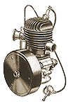
A Flywheel Magneto.
The drawing of this device above, shows the general robust construction adopted,
with the large coils and magnets, and the absence of all delicate parts. The
magnetos, which we inspected in course of assembly and testing, gave an
intense hot spark, which, in these small engines, ensures easy starting with
reliable running under varying loads.
The Works
The foundry, which is specially equipped to deal with
repetition aluminium alloy and bronze work, is accommodated in the old
Villiers Street works. We noted the general high standard of the castings
produced and the good finish secured. The engine and freewheel works is
complete with its own stamp shop, which accommodates ten drop hammers fed by
oil-fired furnaces. The parts are drop forged from strip bar and after
machining and finishing pass to the hardening department.
The general and
automatic machine shops are equipped with power presses, milling machines,
and full-automatic and semi-automatic special purpose lathes and machines
which nave been specially designed to manufacture commercially all the
component parts required down to the smallest pin, nut, or washer. These
parts are subjected to a single high-grade standard of supervision
throughout the different processes of manufacture and assembly.
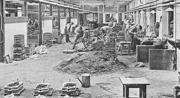
The Foundry.
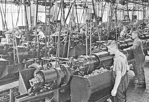
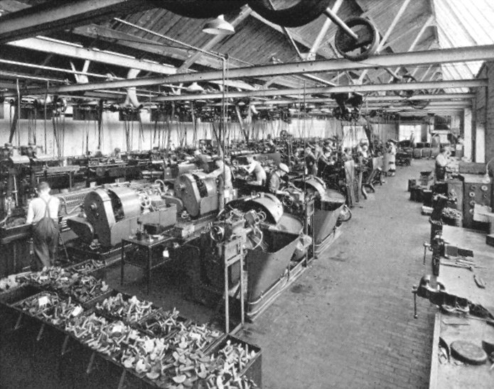
The Automatic Machine Shop.
About eight years ago the Villiers Engineering Company,
Ltd., decided to produce its own type of carburettor, specially adapted to
the needs of the small two-stroke engine and designed to give a compensated
mixture over the whole range of power of the unit. These and other detailed
parts called for an increase in the machinery capacity of the plant, and in
order to meet the new requirements a separate machine shop, specially
equipped for producing the small components and screws from bar, &c., was
built and equipped only last year.
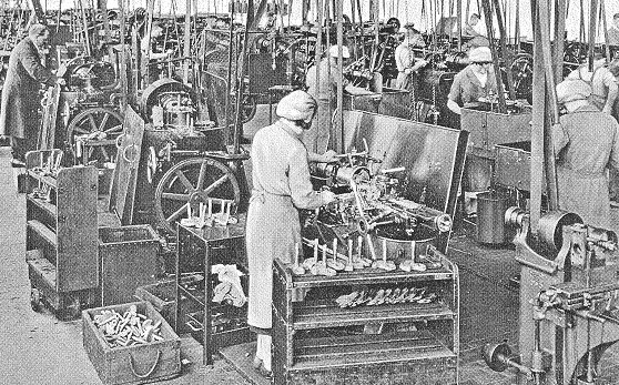
The General Machine Shop.
As the machine tools are largely occupied on repetition
work, a particularly well-equipped tool department is maintained, and there
is a die sinking department to deal with special stamping dies. Attention
has been specially paid to appropriate finishes for the engines and their
component parts, and we noted that many of the brass and bronze components
were being finished by dull chromium plating, while in certain other
instances polishing was resorted to. This finishing work is carried on in
special sections of the factory.
An important new section which has recently
been put to work and which supersedes the original sand blasting equipment
is the shot blasting department, equipped by Tilghman's Patent Sand Blast
Company, Ltd., of Broadheath, near Manchester. The plant consists
essentially of a rotating barrel which is mounted upon four
rubber-covered rollers and is belt driven through spur
gearing. The barrel itself is furnished with a removable
door, through which the castings, stampings, or other
components to be cleaned are introduced.
After it has been loaded and the door fastened the
contents are tumbled and at the same time are brought under
the action of shot blast jets. As the barrel is formed of
perforated steel plates the abrasive material can fall into
a hopper arranged below the barrel, from which it is drawn
up into a cyclone separating chamber by the suction of the
fan. When the shot has been separated from the dust it falls
for re-use into the shot blast machine below, which is
controlled by the setting of the operating levers.
The abrasive is carried along an interior mixing tube and
is delivered by compressed air through the jets into the
barrel. Meanwhile the lighter dust is taken from the top of
the cyclone to a rigid screen type dust collector in which
the dust is arrested and is collected in bags which are
periodically emptied. Clean air passes through the screens
of the dust collector and into the suction of the exhaust
fan and is delivered again to the atmosphere through the
exhaust fan outlet.

The Shotblast Installation.
Brief reference
may also be made to the method of engine assembly. The completed components
and other parts, such as magnetos and carburettors, pass direct to finished
stores, from which they are drawn in batches for assembly. We observed that
following the very close inspection during manufacture very little further
adjustment or fitting was needed, and that practically as soon as the
engines left the assembly bench they ran smoothly on the test bench, which
is modelled on automobile factory lines.
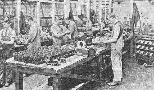
The Engine Assembly Shop.
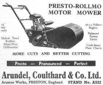
Some typical engines
Besides a standard range of petrol engines specially
designed for motorcycle work, which we do not propose to refer to, the firm
manufactures a wide range of small power units, both air-cooled and
water-cooled, which have found the widest world use. In addition to pumping,
ventilating, air compressing, and lighting plants, industrial driving, and
so on, there is a large range of agricultural engineering uses, including
the driving of forestry saws, fruit-spraying plant, and rabbit-exterminating
machines, in which the exhaust gases of the engines are turned to use. The
engines are also used as auxiliaries on transport vehicles, for starting
other gas and oil engines, for field telegraph sets and for other services.
 |
|
 |
|
3½
hp. Air-Cooled, and 1½ hp. Water-Cooled Engines. |
|
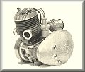
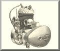
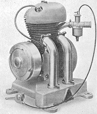
"Mar-Vil" 0.6 B.H.P. Engine. |
One of the smallest engines Villiers have built,
the "Mar-Vil" units, have a designed output of 0.6
B.H.P. at 1750 r.p.m., with a speed range of 1,200
to 1,800 r.p.m. The horizontal cylinder has a bore
of 2in. with a stroke of 1½ in.
Our drawing shows clearly the neat arrangement of
the principal parts, including the compact
flywheel-type magneto previously referred to, and
the firm's special carburettor. The arrangement of
the flywheel is such that not only does it protect
the magneto from water and dust, but also forms an
efficient fan for cooling the ribbed cylinder head,
which is made in an aluminium alloy.
Cast iron is employed for the piston, which
carries two pressure rings, and an inertia ring.
Lubrication of the cylinder is effected by adding
oil to the petrol in the proportion of about 1 part
of oil to 16 of spirit. The ball-bearing crank shaft
may be noted.
The engine is governed by a specially designed
regulating device incorporated within the magneto,
and it is equipped with a novel type of recoil
spring starting handle. A fuel tank is formed within
the base of the engine, and has sufficient capacity
for about 2¾ hours running. |
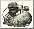
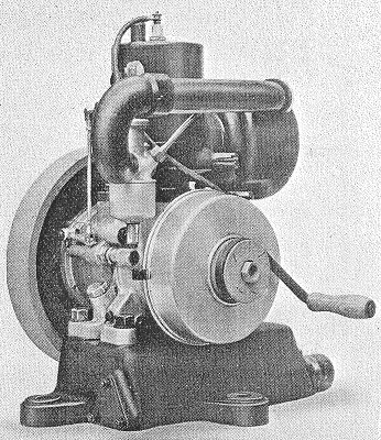
| The complete weight of the engine, including the
tank, is only 29¾ lb. There is also a larger
water-cooled model, which is made in two sizes
designed to develop 1.5 B.H.P. at 1,000 r.p.m., with
a bore of 67 mm. and a stroke of 70 mm.,
corresponding to a cylinder capacity of 247 c.c.,
and 2.6 B.H.P. at 1,400 r.p.m., the corresponding
bore and stroke being 79 mm. and 70 mm., with a
capacity of 343 c.c. Attention may be drawn to the
design of the lipped piston, and the expansion
chamber, which leads by a tube into a base-type
silencer, which gives, we observed, a very quiet
exhaust. The cooling water spaces are quite large,
and they can be easily cleaned. |
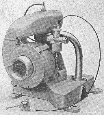
1 hp. Air-Cooled Engine. |
1½ B.H.P. Water-Cooled
Engine.
The carburettor is furnished with a mixture control cam,
and is attached directly to the cylinder casting. We may
mention the provision of a single thin ring, called the
inertia ring, above the top of the first pressure ring on
the piston. This ring is free to rotate and to move up and
down slightly, and it has been found to be very effective in
keeping the rings free from gumming deposits. The governor
is of the centrifugal crank-shaft pattern, and it acts
directly on the carburettor through link gear. The extensive
use of ball and roller bearings may be noted. |