|
Articles from 'The Engineer'
magazine |
|
The Engineer, 21st July, 1871.
The Royal
Agricultural Society's Show at Wolverhampton
Messrs. Joseph Evans and Sons, of Wolverhampton,
who exhibited for the first time, have made a very good beginning, and
give promise of taking a very prominent position as pump manufacturers.
Their 6 horsepower high pressure pumping engine has the pump and steam
cylinder on the same bed plate. We will only remark that it is effective
in design, and well and strongly made.
A bucket and plunger pump, No. 5592, to be driven
by horse power, has one end of the connecting rod working the plunger,
secured to the circumference of a disc; this not only simplifies the
construction of the machine, but as it does away with all gearing,
renders the machinery less liable to breakage in case the horse should
prove restive. They also display a great many lift and force pumps of
various descriptions, amongst which I may particularise No. 6617. This
is a 4 inch rotary lift and force pump. A block on the crankshaft moves
a long wrought iron link, up and down. The link is fixed at one side to
an upright arm, attached to the pump barrel, and is left free at the
other end, and to it is fastened the pump rod, the consequence of this
arrangement being, that the return stroke, in which no labour is
expended, is made very quickly. |
|
|
The Engineer. 25th August, 1871.
Steam Pumping Engine, Messrs. J. Evans & Sons,
Culwell Foundry, Wolverhampton
|
In the accompanying engraving we illustrate a
neatly arranged pumping engine exhibited by Messrs. J. Evans and Sons at
Wolverhampton, during the show.
The engine is six nominal horsepower,
non-condensing, and is fitted with an 8 inch diameter cylinder, 16 inch
stroke. The crankshaft carries a pinion 7 inches in diameter, working into a 28 inch spur wheel on the
pump crank. The pump is double acting, bucket and plunger, 8 inches
diameter, and the plunger is 5.625 inches diameter, with 10 inch stroke.
The valve on the bucket end of the
plunger is of India-rubber, and in the
form of a belt, which covers the ingress
holes. In the forward stroke, the valve
closes on the holes in the plunger, and
in the backward stroke expands with the
pressure of the water, passing through
the holes to the front end of pump,
thence to the delivery pipe. |
|
 |
The suction and delivery valves are of the ordinary flap kind, and the
bucket is metallic, with a gun metal ring. The cranks, etc. are of best
wrought scrap iron, and the piston rod and connecting pin of steel.
It is designed for supplying estates, mansions,
public institutions, etc. and may be arranged for various heights for
lifting and forcing water. By disconnecting the piston, the machinery
may be used for any purpose to which an ordinary steam engine is
applied. The workmanship is very good, and the same may be said of the
design.
|
|
|
The Engineer. 28th July, 1876.
The Royal Agricultural Society's Show at
Birmingham
In my notice of steam pumps last week, I omitted to
refer to one which is novel, in the sense that it has not been exhibited
before. This is the 'Reliable' steam pump, exhibited by Messrs. Joseph
Evans & Sons of Wolverhampton. The most noteworthy feature about this
pump is the fact that in lieu of ordinary clacks the pump is fitted with
a slide valve. This valve is worked by an eccentric on the crankshaft,
which shaft is driven by a dog link intervening between the steam and
pump cylinders. The pump worked very well, and appears to be adapted for
pumping thick fluids.
|
|
|
The Engineer. 22nd July, 1881.
Exhibits at the Royal Agricultural Society's Show,
Derby
Messrs. J. Evans and Sons, of Wolverhampton, showed
Tonkin's patent pump at work. This pump is another of the multitudinous
class of steam pumps with steam moved valves, first invented about
twenty years since. It is very silent and quiet in its action. They also
exhibited some good rotary donkey pumps, coarse and strong, and well
fitted for rough work.
|
|
|
The Engineer. 16th
December, 1881.
The
Cornish Steam Pump
Messrs. Joseph Evans & Sons, Wolverhampton, Engineers
The engraving illustrates a new
type of steam pump, manufactured by Messrs. Joseph Evans
and Sons, of Wolverhampton, and Queen Victoria Street,
London.
Its Motion will be readily
understood from the drawing. As the piston approaches
the end of its stroke, say from right to left, the steam
from the cylinder is admitted by the ports K and M to
the left of the small plunger G, moving it to the right,
by which means the right end of the large plunger D is
placed in communication with the exhaust through the
ports N, and the left end with the interior of the steam
chest B, from which steam is admitted through the ports
R and Q, causing the plunger D, together with the common
slide valve F., to be carried over to the opposite end
of the steam chest, thereby reversing the motion of the
main piston; a similar motion takes place at the
opposite end.
The cushioning of the plunger
valves is most effectively performed by means of small
ports, through which steam direct from the steam chest
flows upon the end of the plunger towards the completion
of its stroke, and this prevents it striking up the
covers and caps; the exhaust steam from the plunger G
passes through the small port S, and thence into the
main exhaust through N. The steam chest being placed on
the side of the cylinder, and the bottom of the steam
port on the same level as the bottom of the cylinder,
the whole of the condensed water is carried out at every
stroke of the piston, whereby the necessity for drain
cocks is avoided. This appears to be a simple and
efficient pump, well adapted for doing a great deal of
work under trying conditions. There are few parts to get
out of order, and the whole machine will obviously stand
knocking about without injury. |
|
|
The Engineer. 20th May, 1892.
Letters to the Editor
Condenser Valves
Sir, In reading your very interesting article on
condensers in the current issue of your paper, we notice a mention of
some firms using valves with serrated edges. In fairness to ourselves, will you kindly mention
that the serrated valves are our patent, and explain that the object of
such serrations is to cause the valve rubber to partly rotate on the grating at each discharge,
thus distributing the wear equally over the whole face. We send you a
sample rubber, and you will notice that the serrations are diagonal, not parallel with the axis. This
simple device prolongs the life of the rubber quite twice as long. The
turning action also has the effect of sweeping off the face any foreign substance.
Wolverhampton, May 18th. Joseph Evans and Sons.
|
|
|
The Engineer. 7th October, 1892.
Compound Condensing
Duplex Pumping Engines For The Water Supply of Managua, Nicaragua
Messrs. Joseph Evans & Sons, Wolverhampton. Engineers
The pumping engine illustrated above has been
designed on the duplex principle, with Messrs. Joseph Evans and Sons'
improvements. There are two 12 inch diameter high pressure, two 20 inch
diameter low pressure steam cylinders, and two 12 inch diameter water
cylinders, all 12 inch stroke. The lever motion for working the valve
gear is fitted with telescopic pieces, having long bearing surfaces,
which are readily oiled from a lubricator provided at the top of each.
This arrangement dispenses with the usual radius links and pin joints,
thus reducing the number of wearing parts. The steam cylinders
throughout are lagged with sheet steel, packed with slag wool, and secured by brass bands, making a very neat and
efficient covering. Cushioning valves are fitted to each cylinder, also
a sight feed lubricator, and additional lubricators for the low pressure
cylinders and stuffing sleeves. The water cylinders are fitted with
easily removable barrels, secured in place by set screws, and are
provided with deep buckets and cup leathers.
The water valves are of Evans' patent rotating disc
type, with brass gratings and guards. The water from the delivery branch
is passed through the tubes of a surface condenser. For convenience of
space this latter is placed at right angles with the centre line of the
main engine. The barrel of the condenser is of wrought iron, double
riveted in the longitudinal seam, and doors of the full diameter of the
condenser are provided at either end for access to the tubes.
The exhausts from the low pressure cylinders are brought together by
means of a forked piece, and led through a two way valve, the latter
being provided for the purpose of turning the exhaust either to the
atmosphere or to the condenser, as desired.
The air pumps are on Messrs. Evans' Cornish
principle, with Tonkin's patent steam cylinders, each steam cylinder
being 5 inches in diameter, and each air pump barrel 8 inches diameter, all 12 inch stroke. The
air pump barrels are fitted with gun metal liners. The valves are on
Messrs. Evans' patent rotating system. All valves are above the water
cylinder, and the capacity is so adjusted that the water level does not
fall below the top of the pistons, consequently a very efficient air
pump is the result. Either one of the air pumps could on emergency do
the work. The engines are capable of delivering over 50,000 gallons of
water per hour. They have to draw their water from a lake l,000ft.
distant, through a 12 inch diameter suction pipe, and deliver through
6,000ft. of 12 inch delivery pipe to the reservoir 180 feet above the
pumps. The working steam pressure is 90 lb. per square inch. The engines
were made for the Nicaragua Company, Leadenhall Street, London, E.C.,
under the supervision of Mr. Heber Duckham, A.M.I.C.E., and are for the
extension of the water supply to the town of Managua. |
|
|
The Enginer. 1st
September, 1893.
Compound Duplex Pumping Engines
Messrs. Joseph Evans & Sons, Wolverhampton. Engineers
We illustrate above a pair of fine
compound duplex pumping engines constructed by Messrs.
Joseph Evans and Son, of Wolverhampton. The engines are
tandem, and fitted with a condenser, not shown, on a
lower level. The dotted lines show the exhaust pipe. As
regards the main valve motion, we may mention that the
high pressure cylinders are worked on the ordinary
Tonkin's patent steam moved valve system, and the main
internal steam plunger in the high pressure steam chest
is fitted with a slide spindle, which drives the low
pressure slide valve through an arrangement of
compensating levers. The object of this lever motion is
two-fold. In the first place, the low-pressure slide
valve face stands out considerably farther from the
centre line of the engine than the high pressure face,
and the lever is a convenient method of bringing in the
centres to suit. In the second place, the width of the
ports and the travel of the valve is greater in the low
pressure cylinders than in the high pressure, and it
will be noticed that the horizontal vibrating lever is
pivoted at the end nearest the centre of the engine, but
the thrust is taken at an intermediate point between the
pivot and the outer end; in other words, it is a lever
of the second order.
It will be observed from the
engraving that the steam chests are low down on the
cylinders, and the bottom of the steam port is below the
bottom of the cylinder in each case, the special object
of this arrangement being to drain the cylinder through
the exhaust without the necessity of drain cocks, and
the arrangement which Messrs. Evans adopt entirely in
their direct acting steam cylinders is found to answer
admirably.
The crossover pipes on the high
pressure steam cylinders are for the purpose of
operating the slide valves so as to drive the duplex
motion which is affected as follows:
Both sides of the engine travel together, but the left
hand side is half the length of the stroke in advance of
the right hand side, consequently one side of the engine
only reverses itself at a time, the other side at the
instant of it neighbour's reversal is in the centre of
its travel and going at full velocity, hence the water
column is kept in motion and there is no appreciable
alteration in the flow of delivery. Should it happen
from any cause that one side of the engine became
disabled, the cross over pipes can be shut off by means
of the cocks provided and shown outside the high
pressure steam cylinders when the valve motion of each
cylinder would be worked on its own account as an
ordinary double action pump, the disabled half being
meanwhile shut off both as regards the steam and water
connections, suitable valves being provided for the
purpose, and any repairs needed could be effected at
once, while the remaining available half of the engine
cou1d continue to work.
In the pumping engine under notice
there are outside packed double-action rams, each 14
inches in diameter, with tail rods at the outer ends to
equalise the displacement, and also to carry part of the
weight of the rams. The water valves are of the patent
rotating rubber disc type, working on brass gratings and
the lift regulated by suitable saucer shaped guards. The
rubber discs which are of special quality, arrived at
after much experimenting, are serrated on the edges
diagonally; the water in upward flow impinges on the
diagonal serrations, and, on the reaction turbine
principle, causes the rubbers to partly rotate on each
beat, thereby equalising the wear all over the faces. It
is stated that cases are known where, after being in
wear for six or eight months, they have become reduced
in thickness more than 50 percent, and yet perfectly
even all over the face. A valve has been sent us by the
makers which fully substantiates this statement. The
centre boss of the valve guard fits in the centre hole
of the rubber and forms a bush, thereby preventing the
wear due to rotation coming on the rubber. A small
amount of lift is allowed in the centre of the valve so
that there may be free rotation.
Though not shown in the engraving,
there are independent air pump condensers in connection
with the engine. The condensers are placed on a lower
level than the main engine bed, to give a good fall for
the condensation water from the steam cylinders. The
condensers are of the injection type, with a large
condensing chamber. The air pump barrels are 10 inches
in diameter by a 24 inch stroke, gun metal lined. The
steam cylinders, which are on Tonkin's patent, direct
acting system, are each 8 inches in diameter by a 24
inch stroke, and are carried on strong distance pieces
overhung from the condenser ends. Convenient doors and
covers are provided throughout to pumps, cylinders,
condensers, etc. for ready access to the internal
portions.
A substantial girder bed plate is
provided under the steam cylinders and back pump boxes,
the forward pump boxes being carried on box feet
connected to the back portion by bridge pipes, which
latter also serve to tie the pump together. Large air
vessels are provided, and all details worked out to best
advantage, so as to be as convenient as possible for
underground use.
The pumps deliver about 1,400 gallons of water per
minute, 360 feet high, with 80 lb. per square inch steam
pressure. They are fitted in a large colliery in the
Newcastle upon Tyne district where a number of large
engines on the same principle, by Messrs. Evans, have
been in successful operation for sometime past. |
|
|
The Engineer. 10th
January, 1896.
Letters to the Editor
Drowned Pumps
It may be in the recollection of
your readers that a few weeks ago the Dungannon
collieries, Ireland, were suddenly inundated by an
enormous body of water tapped from some old workings,
and which unfortunately resulted in serious loss of
life, besides overwhelming the pumping machinery.
Mr. Donald Munro, the managing
engineer of the colliery, advises us that they have been
able to start the large Cornish duplex steam pumping
engine, supplied by us to the colliery, and that it is
working 60 feet under water. We think this will be of
interest to those who have to do with underground
pumping machinery, and shows in a remarkable manner the
capabilities of the direct-acting type of engine.
Joseph Evans & Sons, Wolverhampton.
January 8th. |
|
|
The Engineer. 16th
April, 1897.
Letters to the Editor
Sir, If the notice you give of a
pump regulator in your last week's issue is intended to
bring before your readers a novelty, we would like to
say that the same idea has been applied by us upwards of
ten years ago on a pumping engine for Leamington Spa,
and since then to engines for the Barry Dock, Vale of
Leven, and Vale of Glamorgan Waterworks, etc. We claim
to "go one better" also, as in addition to controlling
the supply, we have provided for the bursting of the
delivery main.
Joseph Evans & Sons, Wolverhampton.
7th April, 1897 |
|
|
The Engineer. 6th
August, 1897.
Evans
Pumping Engine
We illustrate a fine pumping engine
for underground working, lately constructed by Messrs.
Joseph Evans and Sons, of Wolverhampton, for use in the
Miike coal mines in Japan. The engine, as will be seen
by the illustration, is of the direct acting type, and
consists of two complete compound engines, arranged side
by side on bed plates, their steam distribution gear
being so arranged that under ordinary conditions the two
engines work together on the duplex principle, so as to
keep up a continuous flow of water; but when desired the
two sets of valve gear can be disconnected, and one of
the engines can be kept at work while the other is at
rest. The disconnection of the two sets of gear is
effected entirely by the manipulation of certain stop
valves, and is the work of a very short space of time.
The makers claim for this system
that it gives practically the advantages of two engines,
the working of the valve gear and the arrangements and
strengths of the various parts of the pumps being such
that if one engine is stopped for repairs or attention
of any sort, the other engine may with safety be run for
a time at a greatly increased speed, so that but little
pumping capacity is lost until such time as the second
engine can again be put into work. The principal
dimensions of the engine are as follows:
High pressure steam cylinders, 24
inches diameter; low pressure ditto, 44 inches diameter;
stroke, 36 inches. The duty for which the engine was
designed is to raise 2,000 gallons of water per minute a
height of 600 feet. The water to be dealt with is gritty
and impregnated with sulphur, and in consequence is of a
strongly corrosive nature, and with a view to resisting
this corrosive action, the rams, rods, and other working
portions of the pump are made of a specially resistant
bronze.
The engine is provided with a
surface condenser, having tubes and tube-plates of
brass, the water raised by the pumps being employed as
cooling water. The condenser is fitted with two
independent air pumps of the direct acting type. The
steam distribution valve gear of the engines and also of
the air pumps is of the well known steam-moved type
which Messrs. Evans have manufactured for many years
past, the gear of the main engines being Evans and
Tonkins' patent modified form of gear for enabling the
pumps to work in duplex or independent of each other, as
above described.
One steam relay drives both sets of
slide valves on high and low pressure cylinders. The
pump ends are provided with vacuum chambers on the
suction inlets, as well as air vessels placed on the
connecting pipes between the delivery valve boxes, and
all the valve boxes are arranged so that they can be
opened and the valves lifted quite clear of other parts
of the machine. The pumps are of the externally-packed
plunger type, and all parts of the pumps are arranged so
as to be easily accessible. |
|
|
The Engineer. 5th
July, 1901.
Wire
Rope Driven Treble Ram Pump
| In the accompanying engravings we
illustrate the latest design of triple
ram pump made by Joseph Evans and Sons
of Wolverhampton. It is intended for
high lift work in mines, etc. and is
arranged to be driven direct by wire
rope.
On the left is shown the whole pump;
Fig.1 is a section through the valve
boxes; and Fig. 2 a section of the rope
wheel.
As will be seen, this rope wheel is
not of the ordinary grooved type, but is
fitted with a tread, and the driving
rope goes round the rim one and a half
times.
The pump is rated to deliver 18,000
gallons of water per hour against a head
of 750 feet.
The general design will readily be
seen from the illustrations. |
|
 |
 |
| The gearing between the rope pulley
and the crank shaft is half shrouded.
The countershaft and crankshaft are
of mild steel; the latter, which is
provided with circular webs, being cut
from the solid and carried in four
pedestals fitted with gun metal
bearings.
The connecting rods are of steel,
fitted at the large ends with gun metal
marine heads. The small ends are solid,
and are provided with adjustable gun
metal bearings.
The pump rams are of close-grained
cast iron, and are cottered to the
crossheads, which are fitted with
slipper blocks carried by adjustable
slide bars. |
|
The suction and delivery valve boxes of the pump are
interchangeable, as are also the pump barrels, without
an unnecessary number of joints, and the stuffing-boxes
and glands are bushed with gun metal. The pump valves,
which, as will be seen, are of the double beat type, are
also of gun metal, and an air vessel is also provided.
The whole plant is mounted on cast iron girders forming
the bed plate. We understand that this form of bed plate
has been found the most suitable for conveying to the
destination in mines.
| It will doubtless be inquired what
ratio of efficiency is to be obtained
with this system of driving, and on this
point the makers inform us that they
have found that where an installation of
pumps on this principle is operated near
the bottom of a shaft, and near the
driving engine, it works out much less
in cost than would a similar
installation driven electrically. The
reasons for this are that in the former,
the losses of the dynamo and motor are
omitted, and their first cost saved.
A smaller engine at the surface can
moreover be used, since a well arranged
wire rope transmission will give to the
crankshaft of the pump as much as 90
percent of the brake horsepower of the
engine.
Further than this, in the position
where this pump was to work, it was
calculated by the mine engineer that the
first cost of the wire rope transmission
would be as nearly as possible the same
as the electric cable switchboard,
appliances, etc. The net result,
therefore, was that a smaller engine
could be used, and the dynamo and motor
omitted, while the cost of the
transmission system was the same as
compared with an electrical
installation. |
|
 |
In the particular instance of this
pump we are informed that a comparison of the two
systems showed an estimated saving of nearly 50 percent
in first cost, and an ultimate saving of 25 percent in
the subsequent working cost of the rope-driven
arrangement, as compared with an electrically-driven
plant on the same duty.
Of course, if the work of pumping
is required to be done at some considerable distance
from the source of power, the advantage becomes much
more in favour of electricity, because of the upkeep of
the rope, and the losses in it. As a fact, however, the
cost of upkeep of electric cables in mines is very high.
Joseph Evans and Sons inform us that they have supplied
a large number of these pumps for various duties, with
heads varying from 600 feet to 1,700 feet, for both
mines and waterworks. |
|
|
The Engineer. 4th July, 1902.
Boiler Feed Pumps
For the feeding of the main range of boilers at the
Wolverhampton Exhibition, Joseph Evans and Sons have installed a battery
of feed pumps. They are fixed in an extension of the boiler house and
draw their water from a storage tank which is supplied from the
Corporation mains.
Compound Horizontal Feed Pump, Wolverhampton Exhibition.
The boiler pressure is 180 lb. per square inch, and
the discharge water passes through a relief valve loaded to 200 lb. per
square inch pressure when not required in the boilers. There are in all
three feed pumps, all of which are compound, two of them being horizontal and fitted with the makers'
patented Cornish system of compound steam cylinders, and double-acting
outside packed ram pump ends. The steam cylinders are 9 inches. and 16
inches. in diameter respectively, the rams being 7½ inches in diameter,
and all having a stroke of 24 inches.
Each of these two pumps is said to be capable of
delivering 8,000 gallons of feed water per hour against full steam
pressure, and each to be capable of providing the maximum amount of
water which the boilers are likely to be called upon to evaporate. On
the other hand, it is stated that they can run at as low a rate as two
piston feet per minute. The valves in the pump end are of the double
beat type, and are made of gun metal with flat faces. Each pump has a
large air vessel and a vacuum chamber, with the object of reducing
shocks both on the suction and delivery sides to a minimum. Indeed, as
might be expected from pumps made by this firm, all the three are
working with no noticeable noise or vibration of any kind.
| The third pump is of a new type. It is a
vertical compound pump, having steam cylinders 6
inches and 10 inches diameter,
and two 6 inch diameter single-acting rams, all of 12 inch stroke. This
pump possesses some novel features in the valve motion and general
arrangement. It is stated to be capable of delivering about 3,500
gallons of water per hour to the boilers, and is intended to deal with
the ordinary day load.
The makers, who call this pump the Beam Pump,
inform us that this new type of pump has been specially designed for
such work as that of electricity supply stations where the load is very
variable, altering, perhaps, from the maximum to almost nothing in a
short space of time.
They state that some of the more recent types of
pump, notably the duplex type, have not proved entirely satisfactory for
this class of work, and that while the double-ram flywheel type of pump
is satisfactory to a certain extent, it has the disadvantage of not
being able when required to run at a sufficiently slow rate of speed.
Moreover, they urge that the length of stroke which can be given to the
flywheel type of pump is limited, since, in order to get any length of
stroke, the vertical height of the pump itself would be increased beyond
reasonable limits. |
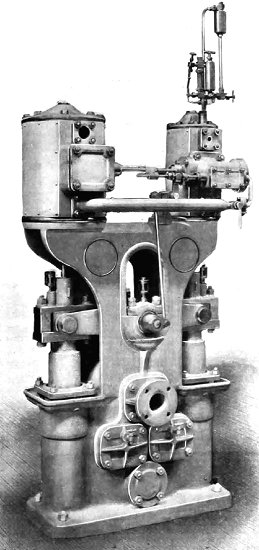
Vertical Compound Beam Pump. |
In the beam feed pump, the crank motion of the
flywheel is dispensed with, but the same vertical arrangement of steam
cylinders and rams is retained, the two sides being connected together
by means of a steel beam vibrating on a central shaft. Each pump ram has
a crosshead and slide arrangement so as to allow for the radial motion
of the beam. The actual travel of the slipper block is small; for a ram
of 12in. stroke it is about l inch. The high pressure cylinder is placed
over one ram and the low pressure cylinder over the other.
The steam
valve motion is driven by means of a small crank on the end of the beam
shaft, connected up by means of a rod to a small ‘L’ shaped lever
mounted on a bracket. This lever, in its travel, moves over a small
auxiliary valve working in the high pressure steam chest, and so admits
steam to either end, as the case may be of a piston working in a small
auxiliary cylinder. This piston is coupled by a spindle to both the high
and low pressure slide valves, so that, when driven over by the steam,
it reverses the slide valves of both steam cylinders simultaneously. The
auxiliary valve already mentioned is also a small slide valve, and is so
arranged that it uncovers the ports at the extreme end of its travel
only. By its use we are informed that the speed of the pump can be
reduced down to a mere crawl. |
|
|
The Engineer. 6th October, 1922.
Electrically Driven Treble-Ram Pump
There has been recently a
considerable amount of discussion among mining engineers
as to the relative merits of electrically driven
reciprocating ram pumps as compared with electrically
driven turbine centrifugal pumps, and although the
latter have admitted advantages, chiefly in their first
cost and the smaller space occupied, many engineers and
mining men still hold the opinion that the treble-ram
pump is more efficient in power consumption, and is more
reliable in operation than the turbine centrifugal type,
especially in cases in which a moderate amount of water
has to be raised to a considerable height.
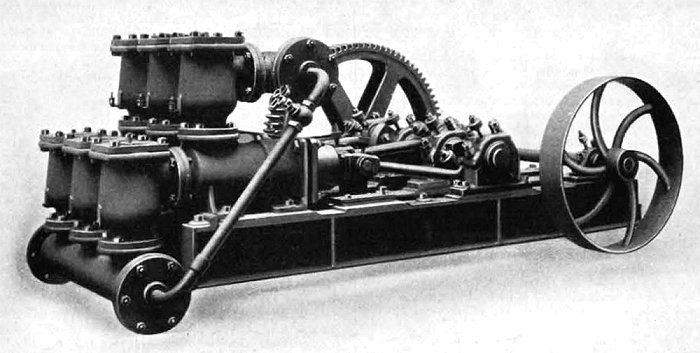
Horizontal, Treble-Ram, High-Head Pump.
We illustrate above a treble-ram
pump constructed by Joseph Evans and Sons (Wolverhampton
Limited, which was installed recently at a colliery in
Scotland where the work of pumping had formerly been
done by turbine centrifugal pumps. The pump has three 9
inch diameter rams, 12 inch stroke, is fitted with
single reduction, double helical, machine moulded
gearing, and on the countershaft there is a belt pulley,
5ft. 9in. in diameter.
Power is transmitted from a 24in.
diameter pulley on a Metropolitan-Vickers direct current
motor by means of a balata belt. The bed plate of the
pump is formed of four cast iron longitudinal girders,
braced together at the end furthest from the pump
barrels by a cross girder, whilst the pump barrels
themselves are provided with bracketed feet, which span
the girders, and are secured by fitted bolts, thus
thoroughly bracing the bed plate girders together at
that end. The slides on which the crossheads work also
span the girders in the same manner, and thus form
additional bracing. The side plates being separate from
the bed, can be adjusted vertically to compensate for
any wear that may take place.
The three working barrels are
interchangeable, while all the six valve boxes are also
separate and interchangeable with one another, so that
in case of mishap or breakage only a comparatively small
portion of the pump need be renewed. The crank shaft has
four bearings provided with heavy gun metal adjustable
steps, giving ample wearing surface, and the pedestals,
being separate from the bed plate are independently
adjustable so as to ensure proper alignment and
facilitate the compensation for any wear that may take
place. The connecting rods are of cast steel with
adjustable brasses at each end. The crossheads are
constructed separate from the rams, and have large
slipper area to take the thrust from the connecting
rods.
The valves are of the maker's high
duty type, having gun metal mitred plates, which are so
arranged as to take the main load when the valves close
on their seats, but water-tightness on the mitring is
not attempted; the slight annular space between the
valve plate and the seating is sealed by means of a
rubber disc on the back of this valve plate, and
superposed thereon is another plate which takes the
pressure of the spring. The valve plate works on a
renewable stalk, and it will be noticed that the sleeve
of this member of the valve is "blind-ended," so that
there can be no passage of water in case of wear. From
many careful measurements of the discharge water under
heavy work, it has been found by the makers that the
volumetric efficiency of pumps fitted with these valves
is frequently 98 or 99 percent.
In the case of pumps of this
construction dealing with water containing grit and
foreign material, these valves are found to have
considerable advantage. The mitre faces of the metallic
portion do not allow grit or similar material to remain
on the sloping faces, but if by any chance such material
should lodge there, the rubber sealing disc will close
over and make the valve water tight in most instances.
This type of valve has been used by Messrs. Evans in
pumps working against heads up to 1600ft. with quite
satisfactory results.
The pump described above was tested
under actual working conditions and without any attempt
specially to tune it up, and the following results have
been furnished by the makers:
Static delivery head against pump,
632.5ft.; friction due to about 750ft. run of 7in.
delivery pipe, 6ft.; vertical height of suction, 15ft.;
friction through 150ft. run of 7in. suction pipe, two
retaining valves and certain bends, 4.5ft. Total head
pumped against from all causes, 658ft.; speed of pump
crank shaft, 41 revolutions per minute; power
consumption, 128 amperes at 485 volts, giving at an
efficiency for the motor of 90 per cent., 74.88
horsepower at the motor pulley; weir measurement, 330.6
gallons per minute; calculated theoretical pump
displacement, 338.7 gallons per minute; volumetric
efficiency of pump, 97.6 percent; horsepower in water
raised against the total head from all causes, 65.9;
showing a mechanical efficiency for the pump of 88 per
cent.
At the same time, a test was
carried out on a nominal 300 gallon per minute turbine
centrifugal pump, working in the same house and under
precisely the same conditions. The turbine pump was
found to deliver 260 gallons per minute only, and the
current used was 230 amperes at 500 volts, giving a
mechanical efficiency therefore of only about 40
percent. The turbine pump has been in use some years,
but has had new impellers and other renewals from time
to time. The Evans treble-ram pump was ideally designed
for a head from 800ft. to 900ft., and would have shown
an even higher efficiency on this latter head or if
designed for the actual head at which it is now working.
The motor driving the Evans pump is also at a
disadvantage, seeing that it is of 150 horsepower,
whereas it is only called upon to give under 75
horsepower in actual running. |
|
|
The Engineer. 18th
March, 1960.
Multi
Cylinder High Speed Hydraulic Pump
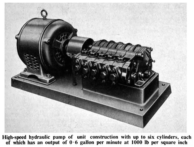
A design of high speed hydraulic
pump or unit construction and with from three to six
cylinders has been produced by Joseph Evans and Sons
(Wolverhampton) Limited, for applications where a
high-pressure pump of very small capacity is required. A
typical example of one of these pumps is shown in our
illustration. Each cylinder has an output of 0·6
imperial gallons per minute, and a six cylinder unit
would thus have an output of 3·6 imperial gallons per
minute. Delivery pressure is 1,000 lb per square inch.
The eccentric shaft of the pump, which is mounted on
roller bearings, is coupled directly through a flexible
coupling to the motor, which runs at a synchronous speed
of 1,000 rpm.
The pumps are suitable for
operation with water, water/soluble oil mixture, or
hydraulic oil as the working medium and the design can
be adapted for use with other liquids. The units can be
provided with spring-loaded relief valves, or
alternatively with automatic unloading valves, which
enables them to run light when operating against closed
stop valves. |
|
 |
|
|
|
|
Return to
History |
|
Return to the Engineering Hall |
|
Proceed to the
1897 catalogue |
|